
Winding Pattern Planning and Control of a Filament Winding Machine for Gas-Cylinders

1
Department of Aeronautics and Astronautics, National Cheng Kung University, Tainan 70101, Taiwan
2
Department of Mechanical Engineering, National Chung Cheng University, Chiayi 62102, Taiwan
3
Advanced Institute of Manufacturing with High-Tech Innovations (AIM-HI), National Chung Cheng University, Chiayi 62102, Taiwan
*
Author to whom correspondence should be addressed.
Machines 2023, 11(6), 635; https://doi.org/10.3390/machines11060635
Submission received: 30 April 2023
/
Revised: 31 May 2023
/
Accepted: 1 June 2023
/
Published: 7 June 2023
(This article belongs to the Special Issue Advanced Design and Control of Inspection Robot)
Abstract
:Filament winding reinforcement is often applied to fulfill high-pressure resistance and is lightweight for gas cylinder productions. This article analyzes the winding pattern and the corresponding characteristics for filament winding cylinders based on the resulting thickness and strength such that the gas cylinders can be made as light as possible. In order to prevent the sliding between the filament material and the cylinder surface during the winding process, a range of winding angles that do not exceed the maximum static friction at every instant is adopted. The gas cylinder geometric structure formed by a complete round of winding using different winding angles is calculated to find the winding pattern that consumes the least composite filament. The winding pattern can also be determined before production to reduce the cost and time for customized products. By sequential contact points of the winding process, motion planning can be carried out for a four-axis filament winding machine.
1. Introduction
In industrial manufacturing processes, steel cylinders for high-pressure gas are often used to transport all kinds of gases for different purposes. To effectively reduce transportation costs, the weight of the gas cylinders needs to be reduced as much as possible while ensuring the necessary strength requirements. Due to the lightweight and high-strength properties of composite materials, they are widely used in various industries. In terms of the manufacturing of pressure vessels, the early application of glass fiber and the current carbon fiber winding reinforcement process have become an indispensable technology for the aerospace manufacturing of liquid fuel containers and airframes [1].
The filament winding machine was first developed with two motion axes to conduct simple winding of workpieces in the 1950s. With the developments of industry and technology, multi-axis winding mechanisms [2] were proposed. At present, three-axis [3,4], and four-axis are the most commonly used filament winding machines. The current research and development focuses on process optimization and controller design to improve the efficiency and cost reduction of the winding process. Abdalla et al. [5] proposed the use of lathe machine to carry out a wet winding process in 2007. The process achieved uniform winding and a good surface finish. The machine was used to manufacture pipe samples of various sizes and other round products that were used for different mechanical tests and applications. In order to calibrate new filament winding, a study on the effect of winding speed is studied by Hashim et al. [6]. Winding angles are also studied by Ma et al. [7] for the quasi-static behavior of thin-walled carbon fiber-reinforced polymer tubes. In 2018, Lu et al. [8] proposed the adoption of an iterative learning sliding mode controller for tension control and estimated the wire tension using a disturbance observer. A robust H∞ control approach with two-degree of freedom (2DOF) for the winding system was developed to reduce the coupling between winding tension and speed [9,10]. In 2018, Xu et al. [11] proposed a tension control method, which combined fuzzy control and PID control by controlling the output of three different driven rollers to adjust the fiber tension and winding speed during the process. In terms of optimized design, Colombo and Vergani [12] proposed the selection of parameters, such as fiber matrix, fiber volume fraction, and winding angle, in the design phase to obtain the optimal manufacturing parameters for glass-fiber-reinforced composite light tubes. With the development of artificial intelligence, learning-based related methods were also applied to winding machines [13,14]. The improvement of winding quality through sensor integration by machine learning was also discussed in [15]. A recent study has developed using machine vision to measure real-time winding angles [16].
To investigate filament winding reinforced gas cylinder production from design to manufacturing, this research focuses on the filament winding pattern selection according to the resulting strength properties and the amount of material used. In this study, the end cap geometry of a gas cylinder is formed by geodesic winding [17]. The strength of the winding patterns of the composite is also analyzed such that a prespecified pressure resistance can be achieved with the least winding filament. The article is arranged as follows: the second section describes the gas cylinder geometry and winding path analysis in detail; the third section analyzes the stress and strength of the gas cylinders reinforced with composite winding; the fourth section describes the motion path planning and realization of a four-axis filament winding machine; and the last section is the conclusions.
2. Description of Gas Cylinder Geometry and Composite String Winding Path
- A.
- Definition of coordinate axes
In this study, geodesics are used for the winding approach, which provides the shortest paths between two arbitrary points on a surface. Four coordinate systems are introduced as follows based on the longitude and latitude coordinates required by the geodesic system and the relationship between the standard local coordinate system.
- (a)
- Standard local coordinate system.
The standard local coordinate system ( is fixed on the machine. In general, one vertex of the gas cylinder is selected as the coordinate origin. Then, the -axis is defined as the axial direction of the gas cylinder directing toward the other vertex. The -axis is kept perpendicular to the ground and pointing upward. Consequently, the -axis is parallel to the ground, and the direction is toward the side where the filament winding head is located, as shown in Figure 1.
- (b)
- Cylindrical coordinate system.
The origin of the cylindrical coordinate system moves according to the coordinate value of the instantaneous contact point of the winding filament on the cylinder. The -axis and the -axis are in the same direction, and the -axis is perpendicular to the -axis and faces toward the instantaneous contact point. The -axis is the cross product of the -axis and the -axis, and the angle between the -axis and the -axis is θ. The corresponding coordinate value in the cylindrical coordinate system of a point P at the standard local system can be obtained by:
- (c)
- Latitude and longitude coordinate system.
The origin of the latitude–longitude coordinate system moves with the instantaneous contact point of the filament on the cylinder. The -axis is the normal vector of the cylinder surface, which directs outward the cylinder. The -axis is tangent to the meridian direction of the cylinder, and its component along the -axis is the same as the direction of movement of the winding head. The angle is the angle between the -axis and the direction of movement of the winding head, and its sign is the same as the -axis component in the -axis direction. The -axis is the cross-product of the -axis and the -axis.
For the winding head moving along with the positive and the negative -axis direction, the relationship between the cylindrical coordinate system and the latitude-longitude coordinate system are shown in Equations (2) and (3), respectively.
- (d)
- Winding coordinate system.
The winding coordinate system and the latitude–longitude coordinate system share the same origin, as shown in Figure 1. The direction of the -axis and the -axis are the same, and the -axis is tangent to the winding path. The -axis is the direction of the cross product of the -axis and the -axis, where is the angle between the -axis and the -axis, and its sign is the same as the -axis component in the -axis direction. For a point P in the longitude-latitude coordinate system, the corresponding coordinate value in the winding coordinate system can be obtained by:
Based on the definition of coordinates, the winding coordinate and the standard local coordinate of the forward and return winding paths can be obtained by Equations (5) and (6), respectively.
where C and S represent cosine and sine functions, respectively.
- B.
- Winding path design
The winding mode mainly determines the complete path of the filament on the gas cylinder. However, the path is determined by winding process parameters and the composite material’s parameters, including the geometric shape of the gas cylinder, the winding filament properties, and the winding angle, etc. The winding angle is defined as the intersection angle between the winding filament’s primary axis and the cylinder’s meridian.
- (1)
- Geometry of cylinder end.
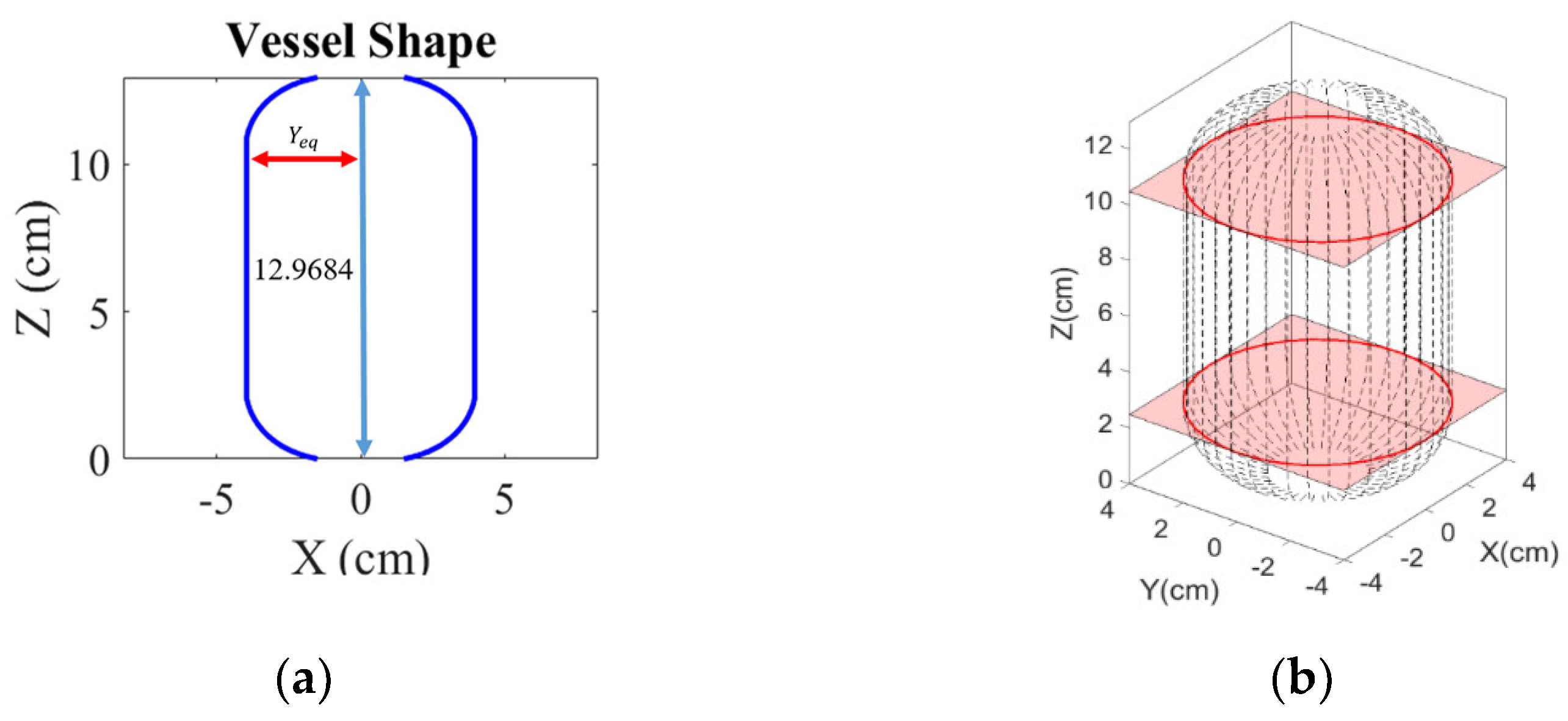
The key feature of the gas cylinder geometry is the shape of the end cap surface, in which the radius of the cylinder body is the radius of the joint ends of the end cap, also known as the equatorial radius (). Based on the static equilibrium and the material properties of the winding strings, an optimal geometry [18] of the gas cylinder end surface can be described by:
where r is the ratio of the total external force on the end cap to the combined force of the storage pressure exerted on the end cap, Yeq is the equatorial radius, Y and Z are the coordinate value of the end face on the -axis and the -axis, respectively. The fiber matrix combination ke is defined as follows.
where and are Young’s modulus, and and are the shear modulus of the composite. The composite material coefficients of carbon fiber strings T700/3234 (carbon fiber/epoxy resin) are referred to [19], where = 132 GPa, = 10.3 GPa, and = 0.25, it results = 0.07803. In order to facilitate follow-up practical research, a small gas cylinder is used, where the minimum radius of the end surface is , the equatorial radius is Yeq = R = 4 cm and the length of the cylinder is L = 8 cm, According to (7), the gas cylinder geometry is shown in Figure 2.
- (2)
- Winding path analysis.
Since the winding angle () of the gas cylinder side−surface is equal to the winding angle at the equatorial radius, determining the cylinder winding angle also determines the winding pattern of the end surface and the cylinder body. However, the friction between the filament and the cylinder must be considered in the end surface winding process to avoid slippage. Therefore, the winding angle () and the process parameters, such as the cylinder speed (), the instantaneous contact point speed (), are both closely related to the velocity (vz) on the -axis. Based on the no-slip consideration for the winding process, the angular velocity ratio can express the static friction coefficient required for the winding process without slippage [20]. For a given static friction coefficient, the following is the no-slip constraint represented by the winding angle and the rotating speed of the gas cylinder.
In Figure 3, the velocity at the instantaneous winding point is divided into two directions and , as presented in Equation (10) and its differentiation can be obtained by Equation (11).
For constant winding rate along the direction, the following conditions are applied.
By Equations (10)–(13), the dynamics of the instantaneous winding point can be described by the nonlinear ordinary differential equation as follows.
Based on the winding boundary conditions vz(0) = 0, Y(0) = Y0 at Z = 0, and the initial angular velocity of the cylinder, the integration of Equation (14) with respect to Z gives.
Subsequently, the rotating speed of the gas cylinder can be represented as:
Since . keeps zero during the winding process, angle between the winding filament and the latitude and longitude coordinate system can be obtained by converting to the standard local coordinate system and substituted in Equation (15), where is the component the winding speed on the -axis direction.
According to the friction and wear properties of composite [21] and the tribological of carbon fiber composite materials [22], the maximum static friction coefficient between the steel cylinder and the carbon fiber composite is about 0.3. Therefore, the constraint that no winding slippage occurs is rewritten as Equation (18).
Since and are real numbers and both Equations (16) and (17) are functions of , the upper limit of the reasonable value of can be obtained with a prescribed geometry of the gas cylinder. For winding motion ppurposes can be described as a function of Z, which meets the limit constraints. Figure 4 shows the limit and candidate functions for , where is described by the proposed function with Z0 = 0. For = 0.9 and the initial value of the processing Z is considered to be 0, then Z can be a quadratic function of time, as shown in Equation (19), for Z = [0, 2.4842], which covers the path located at the cylinder end cap.
Consequently, the dynamic response of can be expressed as (20). In this way, = 0 for Z = 0.
Based on Equation (18) and the geometry of the gas cylinder in Figure 4, the upper limit of the winding angle at each time instant can be determined. For a smooth winding path from the cylinder end to the cylindrical surface, it is reasonable to set the upper limit of the winding angle for both ends the same as the cylindrical winding angle . Assuming that the tape width of the composite filament is 0.5 cm and , the time response of the winding angle and the cylinder rotating speed on the one cylinder end are shown in Figure 5. Owing to the symmetrical property, the response of and for a round-trip winding are as illustrated in Figure 6.
- C.
- Winding path analysis
In practical applications, the cylindrical winding angles are between 10° and 40°. For illustrative purposes, the resulting thickness after one complete coverage will be evaluated for each interval of 5°. Based on the cylinder shown in Figure 2, the round-trip winding path of different cylindrical winding angles are shown in Figure 7. Let denote the angular position difference between the entering and leaving of filament on cylinder end, and denote the angular position difference after a round trip winding as shown in Figure 8 and Figure 9 It can be obtained that:
Suppose one complete coverage winding comprises m full-cycle windings and one full-cycle winding consists of i round-trip windings, where i is determined as the maximum number of round-trip windings without parallel overlapping between filaments. Define as the angular position difference between the i + 1 round-trip winding and the first round-trip winding as shown in Figure 8b, then can be determined by:
where mod (.) is the remainder calculation. Under relational Equations (21) and (22), the path of one full-cycle winding can be obtained for a given . The simulation results of the case study are shown in Figure 10. After completion of a full-cycle winding, the maximum angular position difference can be denoted as and the overlapping angle of the i + 1 and the first round-trip winding is as shown in Figure 11. Then, the requires number of full-cycle winding to have one full-coverage can be obtained by:
where ceil (.) is the unconditional carry quotient. Subsequently, the total number of round-trip winding (tw) for one full coverage is:
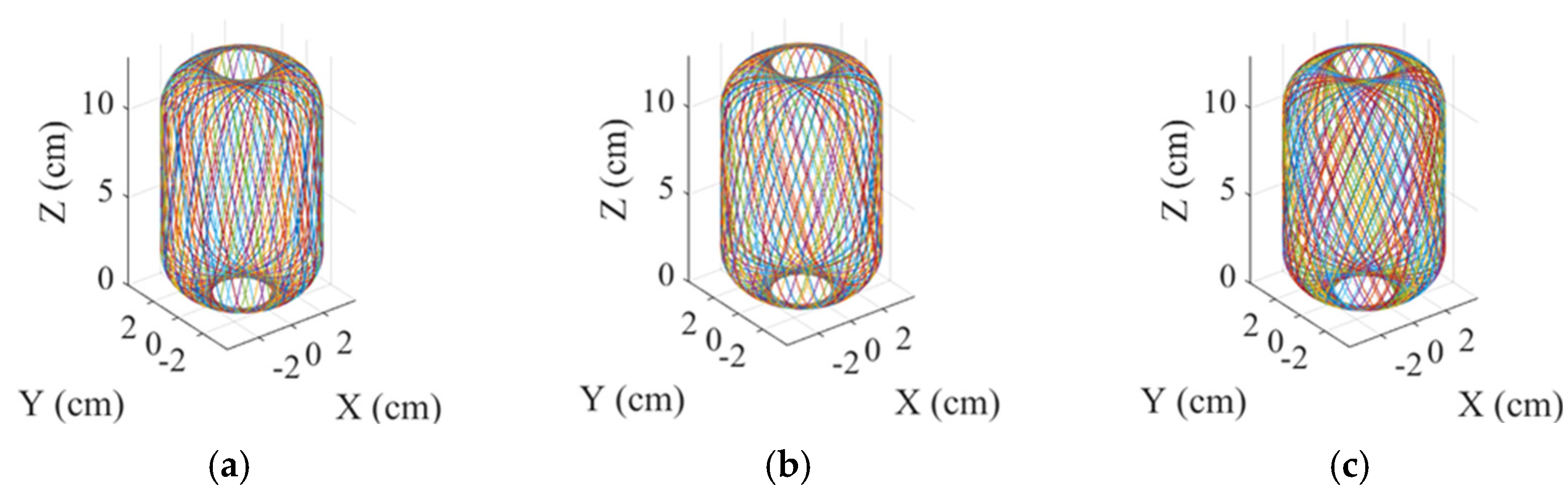
Figure 12 shows paths of one complete winding for different cylindrical winding angles. In Table 1, it shows the Number of round-trip windings to complete one full coverage with different cylindrical winding angles.
Based on the complete winding path obtained, the distribution of filament thickness can then be analyzed to ensure the required strength of the gas cylinder. The average number of filament layers on the cylinder surface with cross-section radius can be determined by:
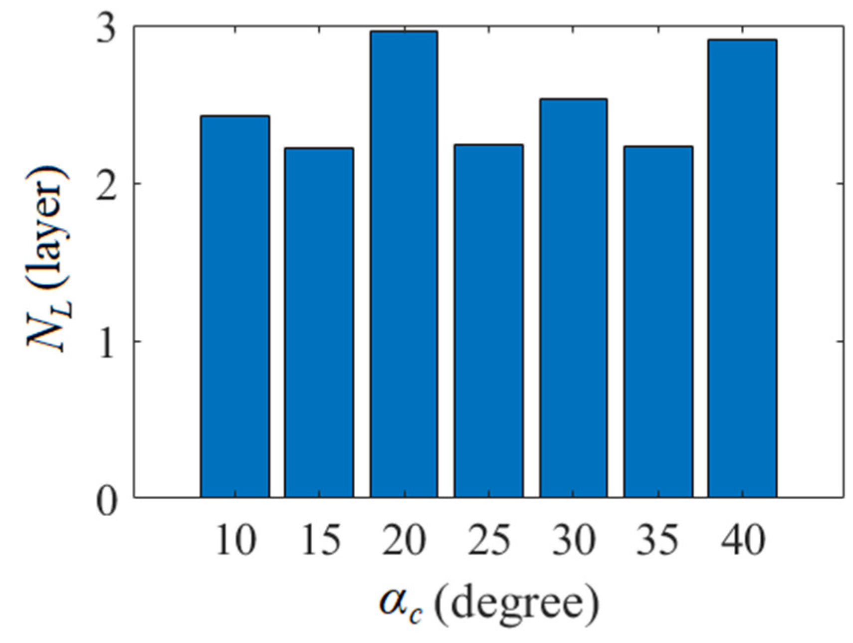
for the case that the gas cylinder has been wound back and forth tw times. By Equation (25), the average layers of coverage at the joint ends = Yeq with different are shown in Figure 13.
For alignment purposes for subsequent cycles, the last round-trip winding of the prior cycle may require winding extra at the end circumference with smallest radius; therefore, NL will be described by
For the study case, the average number of layers at the end of the gas cylinder can be estimated and shown as in Figure 14.
3. Stress and Strength Analysis of Reinforced Gas Cylinders Wound with Composite
After completion of a full coverage winding, the stress and strength analysis can be carried out to ensure the specifications of the resulting gas cylinder. This study uses the ANSYS software to analyze the stress distribution of gas cylinders. Regarding the structural system, gas cylinders use the structural steel listed in the ANSYS database as the inner material. Take the gas cylinder in Figure 2 with a thickness of 0.1 cm as an example. A 1/8 model can be used for computational analysis owing to the geometric symmetry of the gas cylinder, as shown in Figure 15.
For the ANSYS Composite PrepPost (ACP) system analysis, T700 carbon fiber produced by Toray of Japan and EPIKURE 3234 resin is used. The materials data is shown in Table 2, and the second column of 12 K specifications were used for this study.
Take the cylindrical winding angle of 30° as an example. For one full coverage winding, the filament will cover the central cylinder surface twice, contributed by one layer with an angle of +30° and the other layer with an angle of −30°. The end cap is also wound at two different angles round-trip, but the winding angles and the number of layers of coverage are determined by Equations (25) and (26). Take the thickness of 0.05 cm for a single layer of composite filament as an example; the thickness distribution of the outer lining by composite materials can be constructed as shown in Figure 16.
Based on geometric symmetry, the boundary conditions for cross-sections A, B and C, shown in Figure 17, are described as follows. Cross-section A only arrows a displacement along the Z direction, i.e., it is constrained by ΔX = 0 and ΔY = 0. The fact that the membrane thickness of the cylinder end is much larger than that of the cylinder body and the corresponding strength in X and Y direction is very high should be noted. Cross-section B is the symmetry plane of the cylinder, which only arrows displacement in X and Y directions, i.e., it is constrained by ΔZ = 0. For the gas cylinder to withstand a pressure difference of 120 bar, the face C has the pressure boundary condition of 12 MPa outwards.
By adopting the Tsai-Wu failure criterion [23] for failure analysis, it reveals that after completing one full coverage by carbon fiber, the maximum damage value is 0.76157, as shown in Figure 18. As the damage values are all less than 1, the filament reinforcement gas cylinder in this example is capable of withstanding pressure up to 120 bar.
A failure analysis of one complete coverage was conducted for cylindrical winding angles of and the results are shown in Table 3. It illustrated that all seven winding patterns could withstand the pressure of 120 bar. However, due to the fact that the lateral (secondary axis direction) tensile strength of the carbon fiber composite is much lower than the tensile strength of the primary axis direction, the failure index of the cylindrical winding angle of 10° is closer to 1 than the other.
The winding path of the end cap surface is used to calculate the length of the composite materials by piecewise segmented accumulation. Suppose the length of the composite materials used for round-trip winding is , the total length of composite materials required to complete one full coverage winding can be determined by
As shown in Table 3, the winding path with cylindrical winding angle = 15° can be implemented with the least composite materials with a maximum failure criterion index of 0.8264 for one full coverage among the seven cases. It should be noticed that failure index is useful for the vessels used just once. However, for a rocket launching mission, high-pressure gas cylinders are considered disposable, and for this, the analysis can be used to reduce the costs associated with trial and error.
Based on the study in Section 2 and Section 3, the filament winding reinforcement design procedure for gas cylinders is summarized as follows.
- Determine the geometric parameters of the gas cylinder, including the diameter, the length of the cylinder, and the required withstanding pressure;
- Design the end cap surface geometry based on the withstanding pressure of the cylinder, the geodesic description system, and the composite stress matrix combination;
- According to the maximum static friction conditions, select the cylindrical winding angle and determine the number of coverage layers required for the cylinder by stress and strength analysis;
- Realization of path and motion planning based on the winding pattern obtained in step 3. Subsequently, the motion commands for each machine axis can be determined, which will be described in the next section;
- Carry out motion control for each motion axis to complete filament winding.
4. Planning and Realization of Motion Paths of Four-Axis Filament Winding Machine
In this section, a four-axis winding machine, as shown in Figure 19, will be applied to perform the winding process. The motion axes geometry and their physical arrangement will be described in association with the winding motion. Implementation of real-time motion control will also be demonstrated to conduct the winding procedure.
The machine is organized to carry out filament winding for gas cylinders by adding an extra motion axis to a three-axis lathe. Translational motions along the axis (short) and axis (long) are performed by motor 3 and 2, respectively. The rotational motions of the axis are driven by motor 4, and gas cylinder will be mounted along axis and driven by motor 1 for the required cylinder rotating speed .
- A.
- Motion control design
Since the -axis is the primary axis of the gas cylinder, its angle of rotation during the winding is the angle of rotation of the winding coordinate system . It can be obtained by the integral of the rotational speed of the gas cylinder. During a round-trip winding, the forward and return paths require the same amount of angular motions of . Based on the proposed approach in Section 2 (b) and = 15°, the time response of relative to one round-trip winding can be illustrated as in Figure 20.
The rotation axis of the -axis () controls the rotation of the winding head. During the winding of the end cap, the angular displacement is obtained through the geodesic principle , where and is the instantaneous radius and geometric constant of the end cap, respectively. For the cylindrical winding angle of 15° and Yeq = R = 4 cm, cd = 1.0353 can be obtained, and for one round-trip winding can be obtained, as shown in Figure 21.
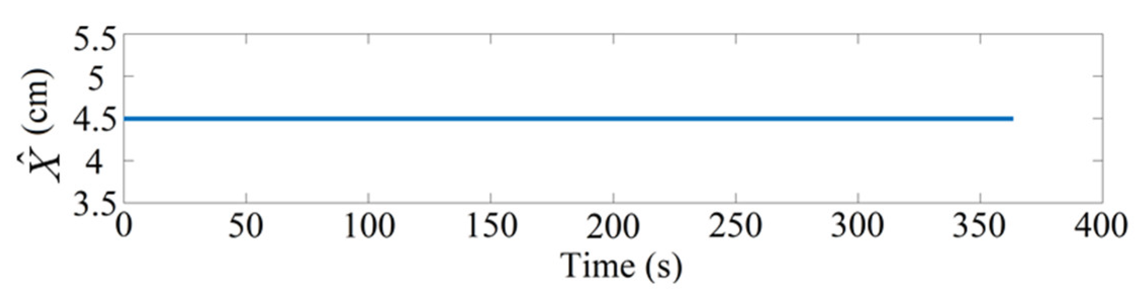
To avoid direct contact with the cylinder surface, the winding head moving in plane will keep 0.5 cm from the cylinder in this illustration. Under a fixed winding radius, the position of the winding head on the axis during one complete winding is constant. Since R = 4 cm and thickness incensement is insignificant during one round-trip winding, the time response of the position along -axis will be kept constant as shown in Figure 22.
The relative position from the contact end point to the winding head roller can be represented by , its vector components to the , , and can be obtained by the angle between the -axis and the -axis, the angle between the -axis and the -axis, and the angle between the -axis and the -axis, as shown in Figure 1. Based on the coordinate transformation described Equations (5) and (6), and assuming that the distance between the instantaneous contact end point on the cylinder and the winding head is of magnitude dt, and its component in the direction is dz, then the position of the winding head roller in the winding coordinate system can be described in coordinate as:
By the constraint relations, it can be obtained that:
Therefore, the position of the winding head roller that moves along the -axis direction can be obtained by adding dz to the -direction component of the contact endpoint. The time response of the winding head roller can then be obtained, as shown in Figure 23 for the demonstrated case.
- B.
- Realization of four-axis motion control
The four-axis motor of the filament winding machine is driven by the motion control interface card through the PCI port of the computer, as shown in Figure 24, such that the motor follows the generated command shown in Section 4 (A).
The Visual Studio C++ was applied as the development environment of the axis motion control interface card and control software. Because the EPCIO driver card can only execute integer pulse commands, continuing to use unconditional carry or round down of the position commands will cause significant cumulative errors. Therefore, in addition to adopting the rounding method, the error caused by rounding up or down must be temporarily stored. When the accumulated value reaches a prescribed threshold, the accumulated integer will be added to the following pulse command of DDA_Time as motion compensation.
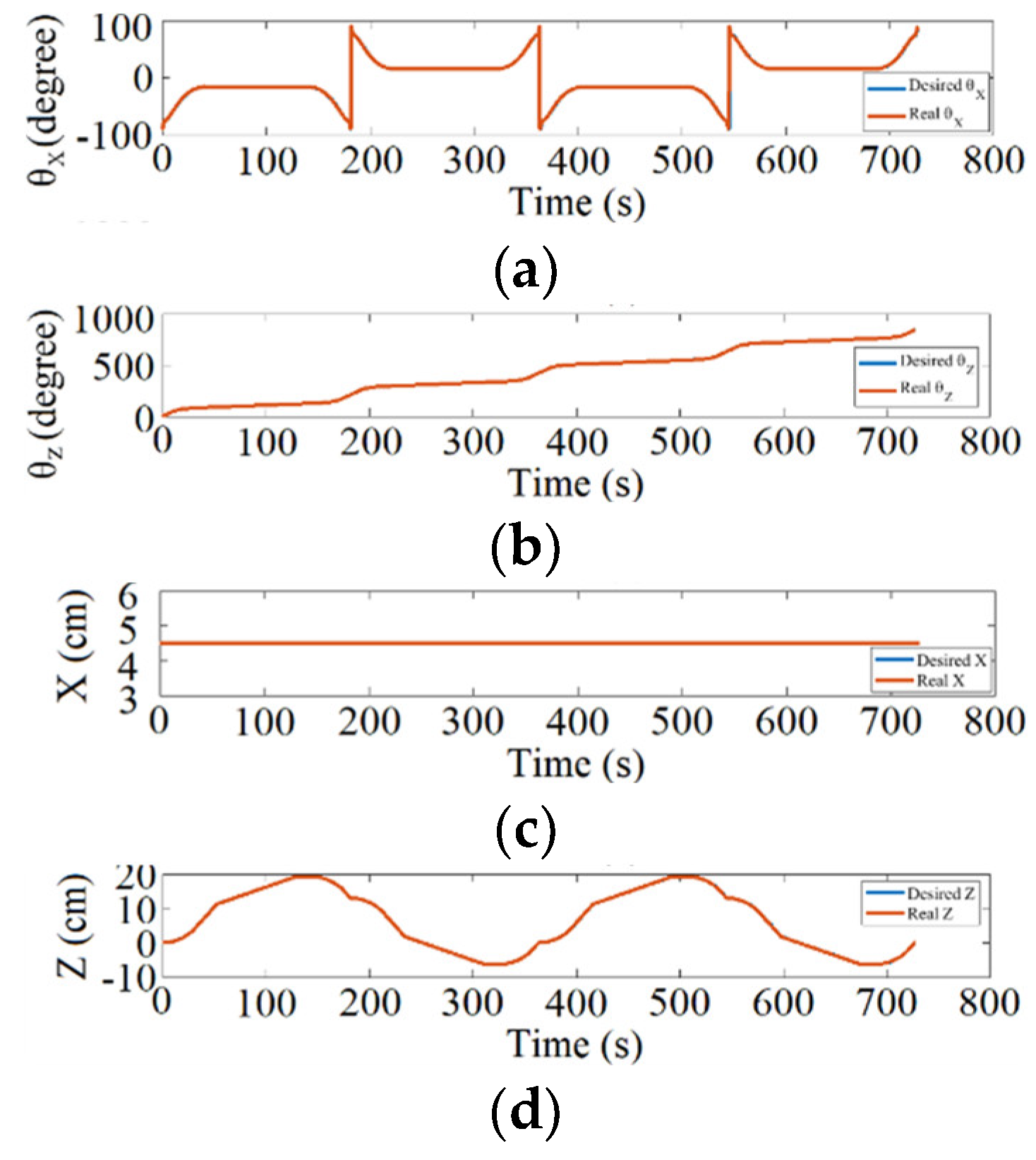
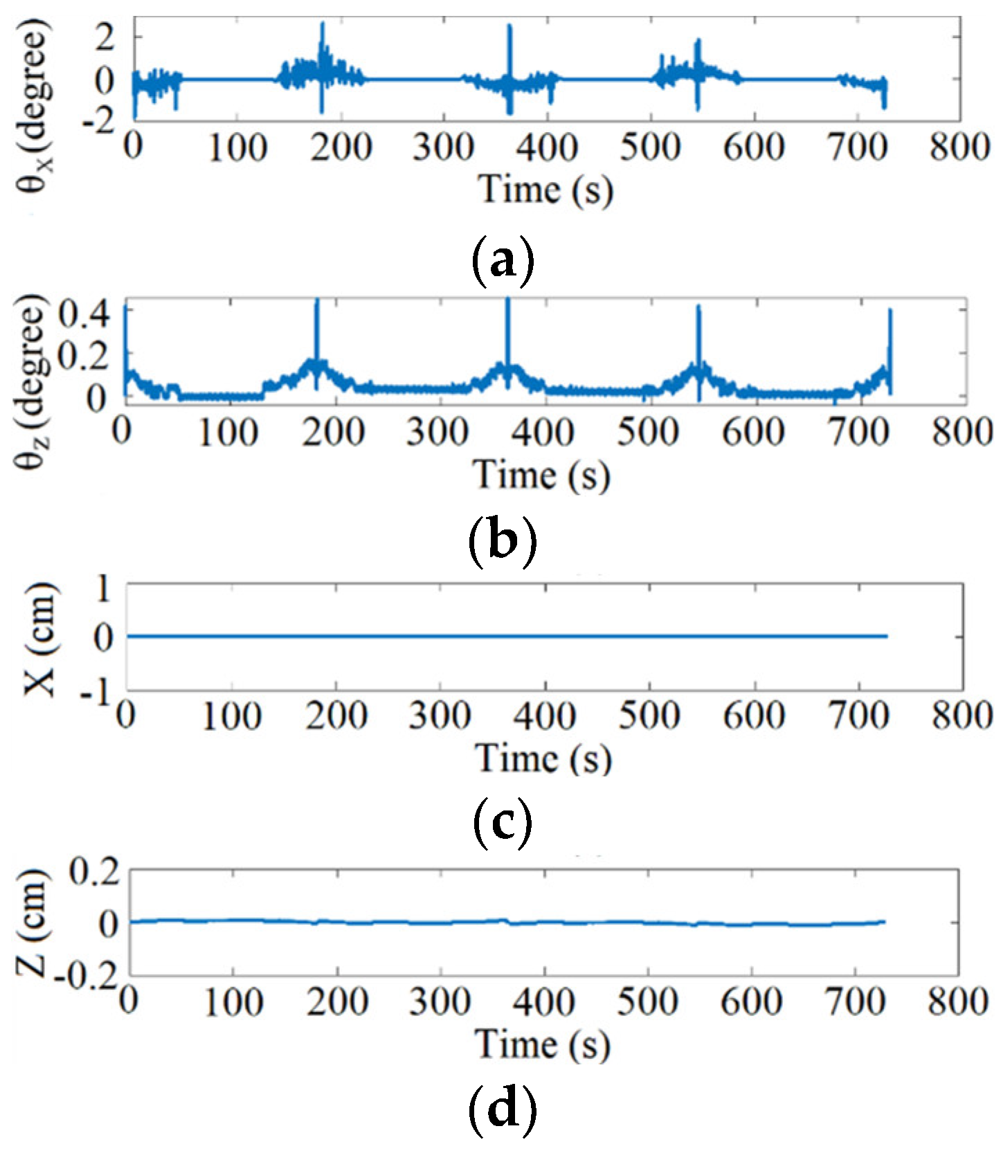
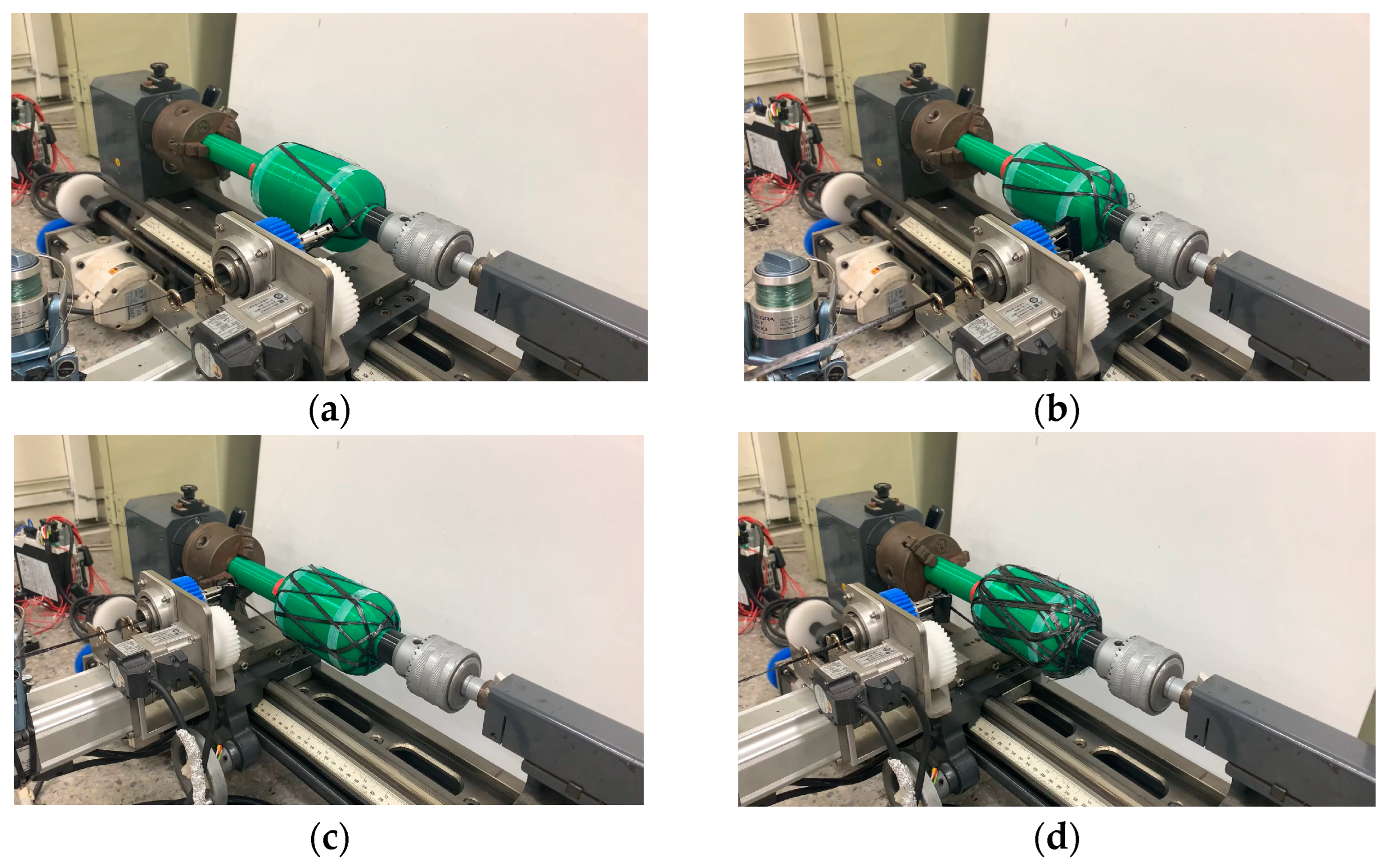
Figure 25 shows the desired and resulting motion response, and Figure 26 shows the error response of the four-axis motion for two round-trip winding. The error can be adjusted by the prescribed threshold and its influence on winding will be limited due to the usage of absolute position reference command instead of incremental type. Figure 27 demonstrates the winding result during two round-trip windings in practice.
5. Conclusions
In this paper, the design of filament winding for gas cylinders under a requested pressure was analyzed based on the cylinder winding angles and cylinders shape. The winding thickness distribution and strength of the pressure vessel were studied according to the winding path and pattern using the least amount of material obtained for the winding process. This article also proposed a procedure to realize motion commands for a four-axis winding machine. Visual Studio carried out implementation with a motion control interface card to confirm the resulting performance. Based on this result, a customized design and development of filament winding for gas cylinders can be systematically conducted.
Author Contributions
Conceptualization, C.-L.C. and H.-T.Y.; methodology, C.-L.C. and H.-T.Y.; software, L.-H.C.; validation, C.-L.C. and H.-T.Y.; writing—original draft preparation, L.-H.C.; writing—review and editing, C.-L.C. and H.-T.Y.; supervision, C.-L.C. and H.-T.Y.; funding acquisition, C.-L.C. and H.-T.Y. All authors have read and agreed to the published version of the manuscript.
Funding
This research received no external funding.
Data Availability Statement
Not applicable.
Acknowledgments
This study is partly supported by the funding of project number MOST108 -2221-E-006 -073 and MOST108-2218-E-006 -021 from the Ministry of Science and Technology. This study also thanks the technology supports by Advanced Institute of Manufacturing with High-tech Innovations (AIM-HI), National Chung Cheng University.
Conflicts of Interest
The authors declare no conflict of interest.
References
- Quanjin, M.; Rejab, M.R.M.; Idris, M.S.; Zhang, B.; Merzuki, M.N.M.; Kumar, N.M. Wireless Technology Applied in 3-Axis Filament Winding Machine Control System Using MIT App Inventor. IOP Conf. Ser. Mater. Sci. Eng. 2019, 469, 012030. [Google Scholar] [CrossRef]
- Minsch, N.; Herrmann, F.H.; Gereke, T.; Nocke, A.; Cherif, C. Analysis of Filament Winding Processes and Potential Equipment Technologies. Procedia CIRP 2017, 66, 125–130. [Google Scholar] [CrossRef]
- Quanjin, M.; Rejab, M.; Sahat, I.; Amiruddin, M.; Bachtiar, D.; Siregar, J.P.; Ibrahim, M.I. Design of PorTable 3-Axis Filament Winding Machine with Inexpensive Control System. J. Mech. Eng. Sci. 2018, 12, 3479–3493. [Google Scholar] [CrossRef]
- Quanjin, M.; Rejab, M.R.M.; Kumar, N.M.; Idris, M.S. Experimental Assessment of the 3-Axis Filament Winding Machine Performance. Results Eng. 2019, 2, 100017. [Google Scholar] [CrossRef]
- Abdalla, F.H.; Mutasher, S.A.; Khalid, Y.A.; Sapuan, S.M.; Hamouda, A.M.S.; Sahari, B.B.; Hamdan, M.M. Design and Fabrication of Low Cost Filament Winding Machine. Mater. Des. 2007, 28, 234–239. [Google Scholar] [CrossRef]
- Hashim, M.F.A.; Ghazali, C.M.R.; Daud, Y.M.; Zainal, F.F.; Faris, M.A.; Si, H.M.; Si, H.S.; Razani, M.S.M. Effect of Winding Speed in Epoxy Glass Composites for New Fabricated Filament Winding Machine. In AIP Conference Proceedings; AIP Publishing LLC: New York, NY, USA, 2020; p. 020034. [Google Scholar]
- Ma, Q.; Rejab, M.R.M.; Azeem, M.; Idris, M.S.; Rani, M.F.; Kumar, A.P. Axial and Radial Crushing Behaviour of Thin-Walled Carbon Fiber-Reinforced Polymer Tubes Fabricated by the Real-Time Winding Angle Measurement System. Forces Mech. 2023, 10, 100170. [Google Scholar] [CrossRef]
- Lu, J.-S.; Cheng, M.-Y.; Su, K.-H.; Tsai, M.-C. Wire Tension Control of an Automatic Motor Winding Machine—An Iterative Learning Sliding Mode Control Approach. Robot. Comput. Integr. Manuf. 2018, 50, 50–62. [Google Scholar] [CrossRef]
- Knittel, D.; Laroche, E.; Gigan, D.; Koç, H. Tension Control for Winding Systems with Two-Degrees-of-Freedom H/Sub/Spl Infin//Controllers. IEEE Trans. Ind. Appl. 2003, 39, 113–120. [Google Scholar] [CrossRef]
- Koc, H.; Knittel, D.; De Mathelin, M.; Abba, G. Modeling and Robust Control of Winding Systems for Elastic Webs. IEEE Trans. Control Syst. Technol. 2002, 10, 197–208. [Google Scholar] [CrossRef]
- Xu, X.-M.; Zhang, W.-X.; Ding, X.-L.; Zhang, M.; Wei, S.-H. Design and Analysis of a Novel Tension Control Method for Winding Machine. Chin. J. Mech. Eng. 2018, 31, 101. [Google Scholar] [CrossRef] [Green Version]
- Colombo, C.; Vergani, L. Optimization of Filament Winding Parameters for the Design of a Composite Pipe. Compos. B Eng. 2018, 148, 207–216. [Google Scholar] [CrossRef]
- Chen, J.; Jang, S.-S.; Wong, D.S.H.; Ma, C.-C.M.; Lin, J.-M. Optimal Design of Filament Winding Using Neural Network Experimental Design Scheme. J. Compos. Mater. 1999, 33, 2281–2300. [Google Scholar] [CrossRef]
- Nachtane, M.; Tarfaoui, M.; Abichou, M.A.; Vetcher, A.; Rouway, M.; Aâmir, A.; Mouadili, H.; Laaouidi, H.; Naanani, H. An Overview of the Recent Advances in Composite Materials and Artificial Intelligence for Hydrogen Storage Vessels Design. J. Compos. Sci. 2023, 7, 119. [Google Scholar] [CrossRef]
- Zu, L.; Koussios, S.; Beukers, A. Integral Design for Filament-Wound Composite Pressure Vessels. Polym. Polym. Compos. 2011, 19, 413–420. [Google Scholar] [CrossRef]
- Ma, Q.; Rejab, M.R.M.; Azman, O.; Aleem, S.A.A.; Tung, N.A.; Asan, S.K.; Rahim, S.R.A.; Praveen Kumar, A. Development of the Real-Time Winding Angle Measurement Device for the Laboratory-Scale 3-Axis Winding Machine. Mater. Today Proc. 2023, 74, 8–14. [Google Scholar] [CrossRef]
- Mayr, A.; Kißkalt, D.; Lomakin, A.; Graichen, K.; Franke, J. Towards an Intelligent Linear Winding Process through Sensor Integration and Machine Learning Techniques. Procedia CIRP 2021, 96, 80–85. [Google Scholar] [CrossRef]
- Vita, A.; Borriello, S.; Landi, D.; Scafa, M.; Germani, M. A Methodological Approach for the Design of Composite Tanks Produced by Filament Winding. In Proceedings of the 16th annual International CAD Conference (CAD’19), Singapore, 24–26 June 2019; CAD Solutions LLC: El Paso, TX, USA, 2019; pp. 288–292. [Google Scholar]
- Tsubota, T.; Shibuya, Y. Strain Response for Damage Detection of Composite Materials with Damage near Circular Hole. Proc. Autumn Conf. Tohoku Branch. 2016, 52, 108. [Google Scholar] [CrossRef]
- Balaji, R.; Mockensturm, E.M. Mechanics of Rotating Wound Rolls. In Proceedings of the Applied Mechanics, Saint Louis, MI, USA, 4–7 June 2006; ASMEDC: Houston, TX, USA, 2006; pp. 503–512. [Google Scholar]
- Sulaiman, S.; Borazjani, S.; Roshanand, A.; Heydaryan, S. Failure Analysis of Aluminum Reinforced Composite Vessel. In Applied Mechanics and Materials; Trans Tech Publ: New York, NY, USA, 2013; Volume 392, pp. 178–182. [Google Scholar]
- Gbadeyan, O.J.; Kanny, K.; Turup Pandurangan, M. Tribological, Mechanical, and Microstructural of Multiwalled Carbon Nanotubes/Short Carbon Fiber Epoxy Composites. J. Tribol. 2018, 140, 22002. [Google Scholar] [CrossRef]
- Ye, L.; Daghyani, H.R. Sliding Friction and Wear of Carbon Fibre-Polyetheretherketon Commingled Yarn Composites against Steel. J. Mater. Sci. Lett. 1996, 15, 1536–1538. [Google Scholar] [CrossRef]
Figure 1.
Relationship between each coordinate axis of the filament winding machine.

Figure 2.
Geometry of gas cylinder. (a) side view; (b) 3-D model.

Figure 3.
Schematics of the winding speed and paths.

Figure 4.
Constrain and candidate functions of .

Figure 5.
Time response at the cylinder end. (a)winding angle; (b) cylinder rotating speed.

Figure 6.
Time response for a round-trip winding. (a) winding angle; (b) cylinder rotating speed.

Figure 7.
Path of one round-trip winding. (a) ; (b) ; (c) ; (d) ; (e) ; (f) ; (g) .


Figure 8.
Schematics diagram of winding pattern and full−cycle path on cylinder end. (a) Angular position difference between the entering and leaving of filament on cylinder end θd; (b) Angular position difference after a full-cycle winding θs.
Figure 8.
Schematics diagram of winding pattern and full−cycle path on cylinder end. (a) Angular position difference between the entering and leaving of filament on cylinder end θd; (b) Angular position difference after a full-cycle winding θs.

Figure 9.
Round-trip winding path on cylindrical surface.

Figure 10.
Path of a set of one full-cycle winding. (a) ; (b) ; (c) ; (d) ; (e) ; (f) ; (g) .


Figure 11.
Filament distribution of one full-cycle winding. (a) filament Distribution with ; (b) compensate angle.
Figure 11.
Filament distribution of one full-cycle winding. (a) filament Distribution with ; (b) compensate angle.

Figure 12.
Path of a full coverage winding. (a) ; (b) ; (c) ; (d) ; (e) ; (f) ; (g) .


Figure 13.
Average layers of coverage at the joint ends.

Figure 14.
Average layers of coverage at the end of the gas cylinder.

Figure 15.
1/8 model showing the inner material of the gas cylinder.

Figure 16.
Cross-sectional view of the thickness distribution of the composite layer.

Figure 17.
Schematics of boundary conditions of the gas cylinder.

Figure 18.
Calculation results of Tsai-Wu failure criterion (cylindrical winding angle).

Figure 19.
The four-axis filament winding machine. (a) rear view; (b) front view.

Figure 20.
Time response of for one round-trip winding.

Figure 21.
Time response of for one round-trip winding.

Figure 22.
Time domain response diagram for the position moving in the -axis.

Figure 23.
Time response of winding head roller along the -axis direction for one round-trip winding.
Figure 23.
Time response of winding head roller along the -axis direction for one round-trip winding.

Figure 24.
Motor control flowchart.

Figure 25.
Motion response of two round-trip winding in (a) ; (b) ; (c) X; (d) Z.

Figure 26.
Response of motion errors of two round-trip winding in (a) ; (b) ; (c) X; (d) Z.

Figure 27.
Result of two round-trip winding. (a) two-round-trip winding; (b) half-full-cycle winding; (c) one-full-cycle winding; (d) two-full-cycle winding.
Figure 27.
Result of two round-trip winding. (a) two-round-trip winding; (b) half-full-cycle winding; (c) one-full-cycle winding; (d) two-full-cycle winding.


Table 1.
Number of round-trip windings to complete one full coverage with different cylindrical winding angles.
Table 1.
Number of round-trip windings to complete one full coverage with different cylindrical winding angles.
| V | Number of Times (i) to Wind One Set | Total Number of Winding Sets (s) |
|---|---|---|
| 10 | 30 | 2 |
| 15 | 6 | 9 |
| 20 | 35 | 2 |
| 25 | 17 | 3 |
| 30 | 11 | 5 |
| 35 | 23 | 2 |
| 40 | 28 | 2 |
Table 2.
Specifications of hybrid composite made of T700 carbon fiber and EPIKURE 3234 resin.
| Composite Carbon Fiber Bundle Tow | 6 K | 12 K | 24 K |
|---|---|---|---|
| Mass per unit length | 400 g/1000 m | 800 g/1000 m | 1650 g/1000 m |
| Tensile strength | 2100 MPa (X) | 24 MPa (Y) | 65 MPa (Z) |
| Young’s modulus | 132 GPa (X) | 10.3 GPa (Y) | 10.3 GPa (Z) |
| Poisson’s ratio | 0.25 (XY) | 0.38 (YZ) | 0.25 (XZ) |
| String density | |||
| Carbon fiber diameter | 7 μm | ||
| Shear modulus | 6500 MPa (XY) | 3910 MPa (YZ) | 6500 MPa (XZ) |
| Shear stress | 75 MPa (X) | 75 MPa (Y) | 75 MPa (Z) |
| Compressive strength | 1050 MPa (X) | 132 MPa (Y) | 132 MPa (Z) |
Table 3.
Length of material needed to complete one full coverage, and the associated failure criterion index value.
Table 3.
Length of material needed to complete one full coverage, and the associated failure criterion index value.
| Cylinder Winding Angle °C | Max. Index Value | Min. Index Value | Equatorial Thickness (Layer) | Total Winding Length (cm) |
|---|---|---|---|---|
| 10° | 0.8548 | 0.1598 | 2.4241 | 2261.5 |
| 15° | 0.8264 | 0.1618 | 2.2243 | 2086.8 |
| 20° | 0.7934 | 0.1329 | 2.9639 | 2792.4 |
| 25° | 0.7787 | 0.1172 | 2.239 | 2115.5 |
| 30° | 0.7615 | 0.1031 | 2.5269 | 2388.6 |
| 35° | 0.7389 | 0.0938 | 2.2343 | 2110.1 |
| 40° | 0.7124 | 0.0869 | 2.9086 | 2737.6 |
Disclaimer/Publisher’s Note: The statements, opinions and data contained in all publications are solely those of the individual author(s) and contributor(s) and not of MDPI and/or the editor(s). MDPI and/or the editor(s) disclaim responsibility for any injury to people or property resulting from any ideas, methods, instructions or products referred to in the content. |
© 2023 by the authors. Licensee MDPI, Basel, Switzerland. This article is an open access article distributed under the terms and conditions of the Creative Commons Attribution (CC BY) license (https://creativecommons.org/licenses/by/4.0/).
Share and Cite
MDPI and ACS Style
Chen, C.-L.; Chen, L.-H.; Yau, H.-T. Winding Pattern Planning and Control of a Filament Winding Machine for Gas-Cylinders. Machines 2023, 11, 635. https://doi.org/10.3390/machines11060635
AMA Style
Chen C-L, Chen L-H, Yau H-T. Winding Pattern Planning and Control of a Filament Winding Machine for Gas-Cylinders. Machines. 2023; 11(6):635. https://doi.org/10.3390/machines11060635
Chicago/Turabian StyleChen, Chieh-Li, Li-Hsuan Chen, and Her-Terng Yau. 2023. "Winding Pattern Planning and Control of a Filament Winding Machine for Gas-Cylinders" Machines 11, no. 6: 635. https://doi.org/10.3390/machines11060635
Note that from the first issue of 2016, this journal uses article numbers instead of page numbers. See further details here.