This tutorial is an introduction to PIC16F84A microcontroller. We will talk about pinout, main features, different GPIO ports, How to use these input outputs pins to blink an LED or control a switch button and how to use timers of PIC16F84A. Let’s start with history of these microcontrollers.
Microchip manufacture a sequence of microcontrollers called PIC. PIC is a Peripheral Interface Microcontroller which was created in 1993 by the General Instruments Microcontrollers. It is controlled by software and programmed in the manner to perform several tasks. There are so many types of microcontrollers available, and some of them are low memory type. These microcontrollers are almost economical, functional and simple to discover.
As compare to different microcontrollers like Arduino Uno which are a little expensive and consists of development boards. But if you do not want to spend much for your project, a single chip pic micro would be perfect for getting you started. PIC18F is a readily available, amazing, and calm competent microcontroller which can help you to add some logic and Intel to your projects. This tutorial is an introduction to PIC16F84A microcontroller. PIC16F84A microcontroller is a very famous pic microcontroller. You may like to check pic microcontroller tutorials.

Introduction to PIC16F84A microcontroller
- PIC16F84A is also known as the beginners’ microcontroller.
- It contains high performance RISC CPU.
- This microcontroller from Microchip was presented in 1998 as a successor to the specific first sequentially programmable PIC, the PIC16C84.
- This is considered to be a starting pickup for learning PIC microcontrollers programming. because it only contains 35 assembly language instructions as well as it only costs less than $2 per piece.
- All instructions are takes one cycle to complete except branch instructions. Size of instruction is 8-bit.
- Maximum operating frequeny is 20MHz. But it can be operated on lower frequency also to save power.
- It is a 8-bit microcontroller. Therefore, the size of data bus is 8 bits.
- Creating a serial programmer for this microcontroller also won’t take a lot of time.
- The PIC16F84A is an 8-bit device which implies the majority of its registers are 8 bits wide.
- It has 1024 words of program memory. If you are working on simple applications then 1024 words of program memory is enough, and this is where PIC16F84A is frequently used.
- Single pin current sourcing and sinking limit is 25mA.
PIN Diagram of PIC16F84A
This is an 18 pin IC, the description of each pin are given below: 
- It has thirtheen GPIO pins and each pin can be used either as digital input or digital output.
- These 13 GPIO pins are shared with PORTA and PORTB.
- PORTA consists of 5 pins from RA0-RA4 and PORTB has 8 pins from RB0-RB7.
Explanation of GPIO pins
- Pins 1,2,3,6,7,8,9,10,11,12,13,17&18:
These 13 GPIO pins can be independently configured either as digital input or as digital output. Also, each pin can either supply or can absorb a maximum of 25mA current per pin. So, accordingly, every pin can drive a LED easily but cannot drive any dc motor or relays. Because, current requirement for LED is generally less than 10mA and dc motor requires greater than 25mA. If you want to interface relay or dc motor, you have to use current driver ICs. Like motor driver IC to interface motor and relay driver IC to interface single of multiple relays. The mentioned 13 I/O pins are assembled into two groups known as ports.
- Port A: contains 5 pins which are 1, 2, 3, 17 & 18 on pinout or RA0, RA1,RA2,RA3,RA4.
- Port B: contains 8 pins which are 6, 7, 8, 9, 10, 11, 12 & 13 or RB0, RB1, RB2, RB3, RB4, RB5, RB6, RB7.
- Pin 4: This is an active low pin known as MCLR (Memory Clear). Obviously, this pin is used to reset the device . Whenever it is kept low while connecting to the ground then it reset the device. Circuit below shows the reset circuit in blue color highlighted region. When user will press the push button, device will reset, otherwise it will remain on.
- Pin 5: This is the ground pin of the IC and must be associated with the negative terminal of the battery or supply voltage.
- Pin 14: This is a supply pin and must be connected to the positive terminal of the power supply. The operating voltage of this device is 5 volts.
- Pin 15 & 16: This is where crystal oscillator connected and the maximum frequency can be used is 20MHz. you can also use a 4MHz crystal but the higher the frequency of crystal used, the quicker the controller works. Also, at higher frequeny, power consumption is also higher. Picture given below shows the circuit diagram for oscillator circuit. Connect both pins OSC1 and OSC2 across 20MHz crystal through two 22pF capacitors.
- You can also consult with the datasheet for further information.

Specifications
| PIC16F84A | specifications |
| Bus Width | 8 Bits |
| Pin Count | 18 (PDIP, SOIC) / 20 (SSOP) |
| Processor Speed | 5 Million Instructions per second |
| Program Memory | 1750 Bytes |
| RAM | 68 Bytes |
| EEPROM | 64 Bytes |
Features of PIC16F84A microcontroller
I/O Pins: There are 13 I/O pins and these pins can be configured individually either as input or as output. Each of these pins source and sinks 25mA current.
Supports ICSP: ICSP stands for In-Circuit Serial Programming. With little careful, you can program the microcontroller deprived of eliminating it from the target board for example in-circuit. This is widely used for in-circuit programming as it contains a USART module.
PIC16F84A Memory: This PIC microcontroller comes with enhanced EEPROM memory. It contains 64 bytes memory that is mainly used to store data and 1K program memory specifies the capacity of code you can burn inside. 68 bytes of RAM (Data Memory).
Watchdog timer: This microcontroller has built-in Watchdog timer. There is an internal timer located under the chip. You can make this timer enable or disable by programming. The timer is mainly used to rest the microcontroller when the program goes wrong or it may enter to the infinite loop.
Registers: There are two types of registers which are as follow here.
- General Purpose Registers (GPR): These general purpose registers are used to store any arbitrary value in which you can operate.
- Special Function Registers (SFR). The special function registers are used to perform various functions which can help to control the device.
Timer: PIC16F84a contains one 8-bit timer that can be utilized in both ways i.e. timer and counter. Furthermore, accompanies internal and external clock select capability.
Sleep Mode: This mode is included the chip that produces a low current power down mode. The sleep mode can be removed using an interrupt, external reset, and watchdog timer.
Power on Reset: This feature is utilized in various other PIC microcontrollers when it is powered on. If there arises a problem in the chip, powering on the device will dismiss it from the loop of any malfunctioning in the device.
PIC16F84a Projects: This version of PIC controllers are mostly used in students projects where the main concern is automation. This is also used in Central heating projects, Production of the temperature data logger, and gas sensor projects. Also used in security systems and setting up serial communication with other devices.
Compilers: PIC controller has different compilers MPLAB C18 Compiler and MikroC Pro for a compiler. The code written in the compiler creates a hex record that is transferred on the PIC Microcontroller.
Ram Memory Banks: the RAM is consist of four banks. Before accessing any register during the time of programming or program writing, you must need to select the particular bank which contains that register. Handling banks may be steep if you write the code in assembly language.
USART module: this microcontroller enhances with the USART module.
Flash Memory: This consist of Flash memory based on 8-bit microcontroller packs. The same microcontroller device can be used for prototyping and production.
LED Blinking Example
- We will see an example of LED blinking with PIC16F84A using Mikro C for PIC compiler.
- In this layout, LED is connected with RB0 pin of PORTB through a 220 ohm resistor.
- 220 ohm resistor is used as a current limiting resistor. It will limit the current to exceed from 25mA which is maximum limit of each pin.
- LED blinking example is used to toggle a LED with a delay of once second.
This circuit is designed with proteus. We can use proteus for simulation of microcontrollers. you can check these proteus tutorial.

- Now, we will learn to program GPIO pins of PIC16F84A to toggle an LED.
- LED is a output device. To drive it, we can used GPIO pin as a digital output pin.
- In order to write code, we need to understand registers associated with GPIO pins.
We are using Mikro C for pic to write code for LED example. But if you have no idea about Mikro C for pic and did not use it before. you can read our step by step guide on how to create project and write code with Mikro C for pic.
There are two registers used for GPIO pins of PIC16F84A and these registers are also same in almost all microchip family of 16F and 18F.
TRISX registers
This register is used to define GPIO pins either as a digital input or output. PORTA has TRISA register and PORTB has TRISB register. Both these registers are bit addressable. For example, if you want to define RB0 pin as digital output pin, Follow command will declare RB0 as a digital output pin.
TRISB.B0=0;
Here TRISB define PORTB direction control register and B0 defines pin number zero or RB0. Initializing any pin with zero using TRISX register will declare it a digital output and if you initialize it as with 1, it will declare it as pin as a digital input pin like this:
TRISB.B0=1;
Some more example for your understanding:
TRISB.B1=1;    // It will declare RB0 pin as digital input pin
TRISB.B2=0;    // It will declare RB2 pin as digital output pin
TRISA.B3=1;   // It will declare RA3 pin as digital input pin
TRISA.B4=0;   // It will declare RA4 pin as digital output pin
TRISB=0x00;   // it will initialize all pins of PORTB output pins
TRISA=0XFF;  // Make all pins digital input pins
Now, if you want to make digital pin logical HIGH, you simply assign it as value 1 and otherwise 0. Like following examples.
PORTB.B0=1;  // assign logical high to RB0
PORTB.B1=0;  // assign logical low to RB1
PORTA.B3=1;  // make RA3 output high or 5 volt
PORTA.B3=0;
This sketch will make the LED toggle with a delay of once second.
void main()
{
TRISB.B0=0;
PORTB.B0=0;
while(1)
{
PORTB.B0=1;
delay_ms(1000);
PORTB.B0=0;
delay_ms(1000);

}
}- Upload hex file to pic microcontroller and you will see LED blinking.
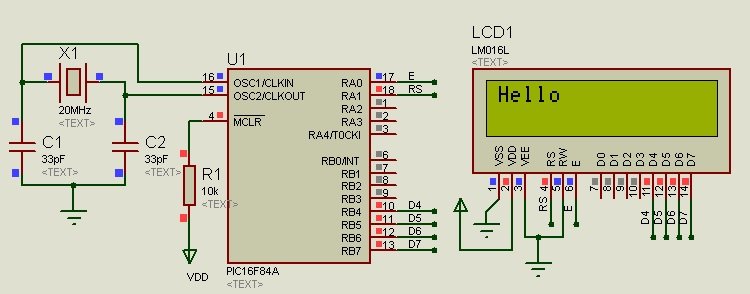
LCD interfacing example in 4 bit mode
This is a example code to connect 16×2 LCD with PIC16F84A microcontroller in 4 bit mode. Connection diagram is shown here.
Code
// it will define registers to be use with LCD
#define LCD_E PORTA.B0 // Enable pin for LCD
#define LCD_RS PORTA.B1 // RS pin for LCD
#define LCD_Data_Bus_D4 PORTB.B4 // Data bus bit 4
#define LCD_Data_Bus_D5 PORTB.B5 // Data bus bit 5
#define LCD_Data_Bus_D6 PORTB.B6 // Data bus bit 6
#define LCD_Data_Bus_D7 PORTB.B7 // Data bus bit 7

// Define the direction of registers
#define LCD_E_Dir TRISA.B0
#define LCD_RS_Dir TRISA.B1
#define LCD_Data_Bus_Dir_D4 TRISB.B4
#define LCD_Data_Bus_Dir_D5 TRISB.B5
#define LCD_Data_Bus_Dir_D6 TRISB.B6
#define LCD_Data_Bus_Dir_D7 TRISB.B7

// Constants
#define E_Delay 500
void ToggleEpinOfLCD(void)
{
LCD_E = 1; // Give a pulse on E pin
delay_us(E_Delay); // so that LCD can latch the
LCD_E = 0; // data from data bus
delay_us(E_Delay);
}

void WriteCommandToLCD(unsigned char Command)
{
LCD_RS = 0; // It is a command

PORTB &= 0x0F; // Make Data pins zero
PORTB |= (Command&0xF0); // Write Upper nibble of data
ToggleEpinOfLCD(); // Give pulse on E pin

PORTB &= 0x0F; // Make Data pins zero
PORTB |= ((Command<<4)&0xF0); // Write Lower nibble of data
ToggleEpinOfLCD(); // Give pulse on E pin
}

void WriteDataToLCD(char LCDChar)
{
LCD_RS = 1; // It is data

PORTB &= 0x0F; // Make Data pins zero
PORTB |= (LCDChar&0xF0); // Write Upper nibble of data
ToggleEpinOfLCD(); // Give pulse on E pin

PORTB &= 0x0F; // Make Data pins zero
PORTB |= ((LCDChar<<4)&0xF0); // Write Lower nibble of data
ToggleEpinOfLCD(); // Give pulse on E pin
}


void InitLCD(void)
{
// Firstly make all pins output
LCD_E = 0; // E = 0
LCD_RS = 0; // RS = 0
LCD_Data_Bus_D4 = 0; // Data bus = 0
LCD_Data_Bus_D5 = 0; // Data bus = 0
LCD_Data_Bus_D6 = 0; // Data bus = 0
LCD_Data_Bus_D7 = 0; // Data bus = 0
LCD_E_Dir = 0; // Make Output
LCD_RS_Dir = 0; // Make Output
LCD_Data_Bus_Dir_D4 = 0; // Make Output
LCD_Data_Bus_Dir_D5 = 0; // Make Output
LCD_Data_Bus_Dir_D6 = 0; // Make Output
LCD_Data_Bus_Dir_D7 = 0; // Make Output

///////////////// Reset process from datasheet //////////////
delay_ms(40);

PORTB &= 0x0F; // Make Data pins zero
PORTB |= 0x30; // Write 0x3 value on data bus
ToggleEpinOfLCD(); // Give pulse on E pin

delay_ms(6);

PORTB &= 0x0F; // Make Data pins zero
PORTB |= 0x30; // Write 0x3 value on data bus
ToggleEpinOfLCD(); // Give pulse on E pin

delay_us(300);

PORTB &= 0x0F; // Make Data pins zero
PORTB |= 0x30; // Write 0x3 value on data bus
ToggleEpinOfLCD(); // Give pulse on E pin

delay_ms(2);

PORTB &= 0x0F; // Make Data pins zero
PORTB |= 0x20; // Write 0x2 value on data bus
ToggleEpinOfLCD(); // Give pulse on E pin

delay_ms(2);
/////////////// Reset Process End ////////////////
WriteCommandToLCD(0x28); //function set
WriteCommandToLCD(0x0c); //display on,cursor off,blink off
WriteCommandToLCD(0x01); //clear display
WriteCommandToLCD(0x06); //entry mode, set increment
}

void ClearLCDScreen(void) // Clear the Screen and return cursor to zero position
{
WriteCommandToLCD(0x01); // Clear the screen
delay_ms(2); // Delay for cursor to return at zero position
}


// Main function
void main()
{
InitLCD(); // Initialize LCD in 8bit mode

WriteDataToLCD('H'); // Write H on LCD screen
WriteDataToLCD('e'); // Write e on LCD screen
WriteDataToLCD('l'); // Write l on LCD screen
WriteDataToLCD('l'); // Write l on LCD screen
WriteDataToLCD('o'); // Write o on LCD screen

while(1)
{
}
}- This code will display text “Hello ” in first line.
- This code can be used with Mikro C for pic.
How to use External interrupt
This example is about using external interrupt pin of PIC16F84A microcontroller. RB0 pin is used to read external interrupts. Microcontroller keep executing its sequential code and based on the request of interrupt, it will turn on the LED and after it receive interrupt again, it will turn off the LED. Interrupt will occur on positive edge. But it can configured for negative edge also.

Code
void interrupt(void)
{
if( INTCON.INTF)   // check if interrupt occurs due to external event on RB0
{
PORTA.B0 = ~PORTA.B0; //  Invert the state of RA0 pin

INTCON.INTF = 0; //  clear this flag bit to clear interrupt signal
}
}
void main()
{

TRISB.B0 = 1; // Make RB0 pin as input
INTCON |= 0x90; // Enable Global + INT interrupt
OPTION_REG |= 0x40; // Make INT as posedge triggered
TRISA.B0 = 0; // Make RA0 pin output
PORTA.B0 = 0; // Make RA0 low


while(1)
{
}
}- As you can see inside the while loop, we are not executing anything and state of LED will change on interrupt only.
- Further explanation of control registers is given in this picture.

How to use TIMER0 interrupt
- This example shows how to use timer0 interrupt. Timer0 will generate a interrupt after specified time and do some work inside the interrupt function.
- For example, code given below toggle the LED after every 4.9KHz frequency. Because, we are using crystal frequency of 20Mhz and CPU will operate at 20/4= 5Mhz.
- We want to toggle LED after every 256 cycles, so select a prescalar of 1:2 .
- So, frequency will be 5M/(512*2) = 4.9KHz.
- You will see a square wave on oscilloscope.

void interrupt(void)
{
if(INTCON.T0IF) //If Timer0 Interrupt
{


PORTA.B0 = ~PORTA.B0; // Invert the state of RA0 pin
INTCON.T0IF = 0; // Clear the interrupt
}
}
void main()
{
OPTION_REG &= 0xC0; // Select prescalar for timer0 2:1
INTCON.T0IE = 1; // Entable timer0 as a interrup
INTCON.GIE = 1; // Enable global interrupts
TRISA.B0 = 0; // initialize RA0 pin as digital output
PORTA.B0 = 0; // make RA0 digitally low initially


while(1)
{
}
}
Some Other Features of PIC16F84A microcontroller
| Features: | |
| Number of pins | 18 |
| CPU | 8 bit PIC |
| Operating Voltage | 2 to 5.5 V |
| Internal Oscillator | Not available |
| External Oscillator | 20MHz |
| UART Protocol | 1 |
you may also like to check pic microcontroller based projects list.