Fun with Normal Maps
About this guide
This guide is split into two sections. The first section gives you some general information about normal maps and explains how they’re used in Octane. The second section is a walkthrough for building your own normal map based on a 3D scan.
Completed project file is here
Part I: General Information
What is a normal map?
A normal map is an image that 3D apps use to very quickly and efficiently add small details in a material. It’s similar to a bump/height map, but instead of just grayscale data that gives a simple height value, normal maps also contain directional data that maps to X, Y and Z axes which can give you better results in some cases and also create certain effects that a bump map can not.
Where do I get them?
The normal map is very often included with most image map sets that make up a PBR (Physically Based Rendering, not the beer) material. Two public domain sites that have PBR materials with completely free CC0 licenses are AmbientCG (formerly known as cc0textures) and Polyhaven (formerly known as texture haven). You can just use the normal map from these sets in your own materials - no need to use all the maps if you don’t want.
You can also get Substance materials (sbsars) either for free (AmbientCG and Substance Source has some), or buy some, and using the free Substance Player, export the normal map.
If you buy models, they’ll often come with a set of texture maps, one of them usually being a normal map.
How do I apply a normal map to a material in Octane?

This part is easy. Octane has a Normal channel in all its material types. Put a normal map in an Image Texture node (this is important - don’t use a C4D bitmap node for this) and feed it into the Normal channel. If you want to adjust the strength of the map, just use the Power slider in the Image Texture node.
This is just like any other texture - the projection must be set properly for the map to look correct. If you apply a material to something and it’s distorted, try also applying it to a plane to see if it’s a problem with the material or the model.
The lighting on my map doesn’t look right - how do I fix it?

Since normal maps store directional data, each axis can either be encoded in a positive or negative direction. Most of the time the X (red) and Z (blue) directions are standardized, but for a variety of reasons, some 3D engines expect the Y (green) axis to be positive (OpenGL type), and some expect it to be negative (DirectX type). As a result, some apps that make normal maps generate them with +Y, and some will generate them with -Y. Octane expects an OpenGL type normal map where green is “up”.
If you find a normal map online and apply it to a plane and it looks like the lighting is a bit off, it’s probably a DirectX type map, and the Y axis is flipped. If you look up close at the map, any pixels that are supposed to be facing “up” should be a mostly greenish color, and any facing down should be a mostly purple color. It’s subtle on some maps, but easy to see once you know what you’re looking for.
Octane 2021 includes a Channel Inverter utility node that you can use to quickly flip the normal map’s Y direction. The Chanphotnel Inverter just goes between the Image texture node with the normal map and the material node. You then select the Channel Inverter node, tick the “Invert green channel” checkbox and you’re good to go.
How do I mix a few normal maps together?

As of Octane 2021, you can now use a Composite Texture Node to mix normal maps! Here’s how that works:
Bring in two Image Texture nodes, and load a normal map into each one. You can mix as many as you want, but in this example we’re just going to do two.
Now bring in a Composite Texture Node. The Composite Texture node requires layers, so in the Shader tab, hit the Add Layer button twice. This will create two composite texture layer nodes for you.
Now you can plug each Image texture node into the Texture input for each layer.
Here’s where the magic happens. Select the composite texture layer node that goes into the Layer 2 slot, and under the Blend Mode dropdown, way at the bottom, there’s a mode called Reoriented Normal. It's a long list, so you may have to place your mouse at the bottom of it to scroll it down to see it depending on your screen resolution.
Select this, and both normal maps will blend together appropriately. The bottom-most layer can be left at the default blend mode, but if you’re going to mix several normal maps together, it doesn’t hurt to select them all and change them to Reoriented Normal.
In addition to changing the power in the image texture, you can control the blend by changing the opacity sliders in each Layer node.
What’s all this I’m seeing about tangent/object/world/camera space?
Normal maps come in two flavors: Object space and tangent space.

Object space normal maps are created specifically for a particular piece of geometry. The colors here are relative to the object’s local coordinate system (or object space). These are often found in game assets, and can sometimes produce higher-quality results, but at the cost of only being usable on the model it was created from. These maps will generally be more colorful than tangent space maps.
Tangent space normal maps are meant to be reusable across a wide variety of models. When you’re hunting for material map sets or SBSARs, this is the type of map you will usually encounter. These maps are mostly a “neutral” cornflower blue color that tells the engine not to alter the normal for that pixel. Any other combination of red, green and blue tells it to shift the apparent normal one way or the other relative to the polygon’s true geometric normal.
When building normal maps, there needs to be a set of coordinates (a ‘space’) that the normals are relative to when they’re being remapped. Object space normal maps use the object’s local coordinate system to know which way is “up” (y) or “forward” (z). Usually this is handled in the sculpting/baking portion of the asset creation process and we’re not going to get into that here.
Tangent space normal maps can be generated in a world or camera space coordinate system. This just means that it’s using the world or camera’s x, y, and z coordinates to determine what is considered up, down, left, right, forward, or back, so it can determine what color to make that pixel which will tell the material how the light should be handled. This is explained in more detail in the walkthrough section where we’ll build a tangent space normal map using both methods.
How do I make my own normal maps?
There are applications out there that will make them for you based on a 2D image, but the results will vary depending on the quality/lighting of the image and how good the app’s algorithm is. There are also apps that will take a bump/height map and make a normal map from that. That sometimes will give even better results depending on how detailed the bump is.
The most accurate way to generate normal maps is via 3D data. Cinema 4D itself has a method of baking object or tangent space normal maps based on sculpt data. Octane also allows you to build a normal map based on geometry. In the next section, we’ll take a look at how to do this.
Part II: Walkthrough - 3D Scan to Normal Map
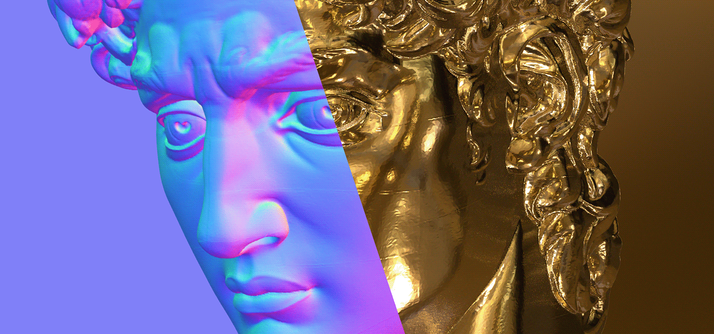
Let’s say we want to create a coin with Michaelangelo’s David on it. We want the image to look like it has some dimension to it. but we don’t want the original one million polygon 3D scan or displacement to weigh the scene down and add to the render time.
Here’s how we can go about making a normal map out of the 3D scan. This method can also be used to make repeating patterns or labels/decals out of geometry.
Scene Setup
The very first thing we should do is set up our aspect ratio. Let’s hit Control or Command-B to bring up C4D’s render settings. 1:1 is typically the most versatile map aspect ratio, and 2k should be good enough for this case. In the Output section, let’s set it to 2048x2048, and make sure Octane Renderer is set as our renderer in the dropdown.
Now let’s grab the 3D scan of David. Scan the World has a large collection of free 3D scans, so let’s just find David and download the STL file.
Note: newer versions of C4D support STL - for older versions you’ll either have to find a converter or find an OBJ version of a 3D scan.
Note: newer versions of C4D support STL - for older versions you’ll either have to find a converter or find an OBJ version of a 3D scan.
Now we can use Merge Objects (ctl/cmd-shift-o) in C4D to bring this in. The default of 1cm is fine for the scale. This scan is about a million polygons, so depending on your CPU, it might take a few seconds to load in.

To make this object easier to manipulate, we’ll want the axis in the middle of the geometry. This is a simple fix - making sure we’re in Model mode (not points, edges or polygons mode), we can select the object, hit shift-C and type “axis center” (or Mesh>Axis>Axis Center in the menus) to bring up the Axis Center tool. Leaving everything at default, we can just hit “execute”. Now we can zero the coordinates out by hitting the Reset Transform button (Reset PSR in earlier versions). That will center up the model in the world.
Let’s add an Octane Camera and set the focal length to something like 85 for a nice portrait shot.
Since a normal map takes its information from the geometry’s normals and not from lighting, we don’t need to light the scene at all.
From here, there are two paths we can take.
The quick and dirty way: Geometric normal AOV + world space
In this method, we’re going to use Octane’s Geometric Normal AOV (render pass) and the world’s X, Y, and Z coordinates to generate our map. This is what’s known as World Space, as opposed to Camera Space or Object Space. This method involves a lot less in the way of setup, but limits the amount of camera freedom we have.

Camera setup
So let’s set our camera’s coordinates so P.X and P.Y are zero, and let’s bring P.Z back to -400 cm or so. We need to double check that the camera’s R.H, R.P & R.B values are always zero for this method to work properly.
Model setup
Now we can rotate the model (not the camera) to frame David up. We can move the camera along X, Y and Z, but If we rotate the camera, the normals won’t align properly with the world space and the final map will look wrong.
Background setup
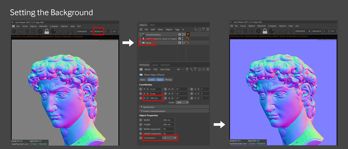
Now let’s come up to the viewport and switch from DL (Direct Lighting) to Normal (Geometric Normal). All of a sudden this looks kind of like a normal map, but the background is gray, which won’t do. We want it to be that neutral cornflower blue that tells the material that these pixels shouldn’t contribute anything to the normal map.
The easy way to deal with this is to put a plane in the scene, and set the Orientation to -Z. Let’s move it back in space a bit so it’s behind the model, but still fills the frame.
Saving
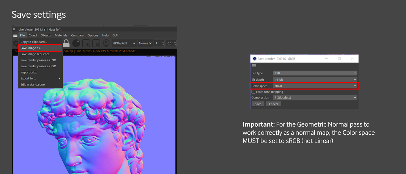
The fastest way to do this is to go into the Live Viewer and save this out as either an EXR or a PNG. We can also set up a Geometric Normal AOV and export it using passes, but this is meant to be the quick and dirty method, so we’ll get into AOVs in the next section.
Important: For this method to work, the color space needs to be set to sRGB, NOT Linear (even for EXR format). For EXR, PIZ compression usually offers the best quality for the file size.
More setup, more flexibility with OSL and a Custom AOV
In this method, we’re going to use an OSL (open shader language) shader in a custom AOV (render pass) to generate the normal map.
Unlike the Geometric Normal pass which is relative to world space, the normal direction in this shader is in camera space (based on the camera angle relative to the geometry). This is great because it gives us the flexibility to orbit our camera around our models freely and frame up our scene more easily than trying to rotate models into place.
Big thanks to @roeland and @jobigoud in the Octane Forums for help with this :)
AOV/OSL Setup

Let’s head back to C4D’s Render Settings by hitting Ctl/Cmd-B or by just clicking the Render Settings button in the upper right (clapboard with the gear). Now let’s go down to the Octane Renderer settings, and in the Render AOV Group tab, tick the Enable checkbox to tell Octane that we want to use AOVs.
Now let’s hit the Add render AOV button, go into the Custom category and choose Global tex. This will override all materials and textures on everything in the scene for this pass.

Under the Render AOVs twirldown, we can see that it added AOV:Global tex. Right now it’s not doing anything because it needs a texture loaded in. In the Texture section, there’s a small down-arrow button directly to the right of the word “Texture”. Let’s hit that, go into plugins, in c4doctane, and choose OSL texture.
If we click the bar in the middle that now says “Osl Texture”, an OSL editor will show up in the Attributes Manager. We just need to paste some code in there.
shader OslTexture(
output vector c = 0)
{
c = transform("world", "camera", vector(N)) * 0.5 + 0.5;
}

If we start the render again, we’ll notice a new toggle at the bottom of the Live Viewer called Glob1 (global texture 1). That’s the new custom AOV we just made. If we hit that, we’ll see what looks like a washed out Normal map. We can see what the final image will look like by choosing HDR/Linear sRGB from the dropdown. This AOV works in a Linear color space, so if the default sRGB tonemapping is selected, it’ll look washed out. Changing the color space here has no effect on the final output, it’s just for visualization purposes.
Background Setup

As we orbit around the model, we’ll notice the texture on David updates properly, but the background changes color. This is because as the angle of the normals of the plane change relative to the camera, they output different values. We really want to lock this in so the background is always flat-on to the camera. Easy enough to do, we just need to parent the plane to the camera by nesting it, and then hit the Reset Transform button so all the coordinates are zeroed out in relation to the camera, and then shift it back in Z a bunch so it’s behind the model again, but filling the frame (we can always make the plane larger if need be). Now as we orbit around the model, the background stays the correct neutral blue, and the model updates properly as we move around it.

Saving
We can export this as an EXR from the Live Viewer using the Linear color space, and the output will be correct. PIZ compression is a very good option for keeping the file size down.
We can’t save a PNG in the linear color space from the Live Viewer, so if we need it as a PNG, there are extra steps that must be taken. Let’s hit Ctl or Cmd B to bring the render settings back up. We can uncheck Save since we don’t need the beauty pass.
In the Render AOV group, we’ll need to select PNG, 16-bit, and put a file name and path in here.
Here’s the important part. In the Main tab, we need to set the color space to Linear sRGB. What shows up in the picture viewer will probably be completely off, but the final normal map file will work correctly.
The Normal Node
A new Normal node was added in Octane 2021.1. This node does the same thing as the OSL code we put in, but accessing it takes a little extra work. To get to this, we’ll need to launch the node editor. We can do that in the settings by hitting the Node Editor button in the Render AOV group section of the Octane Renderer settings.
Now that we have that up, we can see the node network for the AOVs. If we hit tab, spacebar, or shift-c while the node editor is active, we can search for Normal and hit enter to add that in. If we select that node, we can set the Coordinate system to Camera, and click Normalize Results. Now if we hook that up to the Global tex’s Texture input instead of the Osl Texture, we should get the same result.
This node gives you access to all kinds of other data that you can then use to create some interesting effects, including Object Space normals so you can build normal maps that are custom tailored to a specific model.
Applying the texture to the coin

We now have our final normal map! Time to apply it to the coin. For the geometry here, we’re going to use a circle spline that’s been extruded rather than a cylinder because we don’t want to get into projection issues. Specs for this are: 6cm Circle spline, intermediate points Natural/60. Extrude is 1cm. Bevel is round, 0.1cm.
Now let’s bring in a gold material. The RGB IOR gold found at the end of this guide would make a good base. This will look nicer if we bring the Roughness to 0.15. Let’s duplicate that material since we only want David on the cap.
Let’s open up our cap material in the node editor and bring in an Image Texture node (important). We can load our normal map into that, and then plug it into the Normal channel.
Now we need to apply the base material to the geometry, and then the material with David to the right of that (so that it overrides the base material). If we select the texture tag for the David material, we can restrict it to just the top cap by putting C1 in the Selection field. If we wanted it on the bottom cap as well, we could duplicate the tag and change it to C2 in the second copy.
Completed project file is here


