
Normal map creation process
This tutorial will cover nearly everything you will need to know about creating normal maps; This includes the low oly model, high oly model, correctly laying out your UV's, how to mirror a normal map with an object, baking the texture, adding details in photoshop and much more.
Normal map basics:
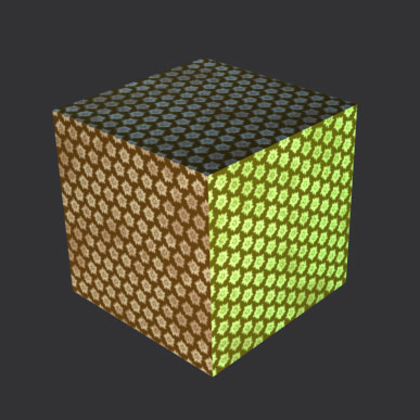
Let’s start very simple. A box, it doesn't get much simpler than that. Let’s place texture pattern on it as well and place some lights around the cube so we can see how the lighting works with the geometry, and how the textures change. With a simple 6 cube and all the faces laid out in the 0 to 1, this is what you will get.

This is as simple as you can get in 3D, but it is by NO means exciting or interesting. We will get into more complexed objects, but for now, let’s start at the basics and work our way up.
To create a high poly model and bake it to a low poly, you need to follow these steps.
Create a high poly model based on the low poly version.
Keep both models in the exact same position.
Have your UV's laid out in the 0 to 1 space. Anything that is outside the 0 to 1 will not be calculated. (There are ways to overlap, and we will get to that soon enough.

This is a very simple (high polygon) version of the box. The poly count is 492 tris, WAY too high for a simple box. For this example, I laid one face of the low poly to the full '0 to 1' UV space, and moved everything else outside of the renderable area. The reason for this is so only one face will be calculated which will be applied to the other faces soon enough.
To bake out a normal map from a high poly model to a low poly model, select the low poly and press 0, not on the number pad, but the zero located above the o and the p keys. Doing this will bring up this screen. I shrunk all of the sub-menus except one so it won't take up too much space
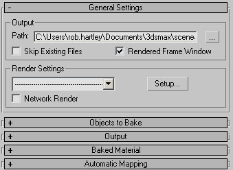
There are 5 sub-menus in this option screen; the first is “General Settings”. Usually leaving this the way it is gives good settings, but in this screen, you can tweak the rendering to better suite your normal map rendering needs. Pressing the 'Setup' button brings up your max' 'Render Setup' screen (same as pressing 9). In most cases; if not all, it is best to use 'Default Scanline Renderer' located under 'Common/Assign Renderer' within the 'Render Setup' window.

The second 'sub-menu' is called 'Objects to Bake'. Here is where you pick the high res object to use as a reference.
(Please note that this menu is also used for baking out other things such as shadows, diffuse, shadows, height maps and many more. Because of this, not all of these options are required all of the time.)
If you do not see what is on the screen to the left, don't panic. If it is all greyed out, simply select the low poly model. One thing that will always appear different is the 'name' of the object, in this case I have 'Box05' selected to bake out, your object will most likely be name differently.
The 'Selected Object Settings' should almost always be enabled, and the 'Padding' refers to the amount of pixels that should bleed out on the edge of every UV edge. This should always be set to at least 2. The reason for this is so every edge lines up with the correct details and will not have line artefacts in the final render.
'Projection Mapping' is where you select the high poly model. Click the 'Enabled' check box, and click the 'Pick' button. A menu will appear showing the visible geometry in the scene you wish to bake a texture based off of. Please note that you must have your high poly version visible in order to see it in the menu.
After selecting your high poly mesh, choose the UV's you wish to use, this will usually be set to 1.

The third sub-menu is called 'Output'. This is where you choose which type of texture to bake out. All of these options can be used to copy textures from one UV space of one model to another UV space of the same or different model.
Complete Map:
Specular Map:
Diffuse Map:
Shadow Map:
Light Map:
Normals Map:
Blend Map:
Alpha Map:
Height Map:
Each one of these options has a specific purpose, but I will leave it up to you to explore with them and see what does what. For this tutorial, I will only be focusing on the normal map option.

Press 'Add' and select 'Normal Map' from the list. A few things will automatically fill out for you. First you will see the name of your object, next to it will be the texture you will be baking out, and finally the texture size you are looking for.
Below, you will see an option beside 'File Name and Type'. This is where the location of the texture and its name will be baked out to. Click on the triple dotted box [...] to the right of it if you choose to chance the location.
Below that is where you choose the size of the texture. I will get into the importance of this later on, but for now, 512X512 should be fine.
Once you have filled everything out, press the 'Render' button on the far bottom left. You will see a rendering screen pop up. This is only a preview window, not the actual normal map itself. The reason for its lack in color is to visually show you where information was lost. I will go into detail with this later on, for now, this asset is too simple to demonstrate this functionality.
Before I show you any rendered images, I should go into a bit of theory behind normal maps.
This is the basics of smooth groups and hi-poly model baking. This was borrowed from http://wiki.polycount.net/Normal_Map
This theory is important to understand before you start to bake out high to low poly models. Without this foundation, you will run into many issues down the road.
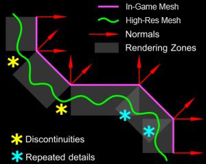

The image on the left is a model with hard edges. This will cause some serious problems which you can see in the yellow and blue stars. These areas either calculate the normal details twice, or not at all.
The image on the right is a model with smoothed normals throughout the entire model. This will allow for much closer resembling details when you bake out your normal maps.
If you choose to create a high poly version of a low poly model, keep this diagram in mind. Depending on where you create your details, and where you want things to be, different smooth groups will give different results. This also applies to models that you are taking over. Do not assume you know how it was created or modeled. Study the model, as well as the normal maps you have.
For the sake of this model (the dumpster) I am giving each side their own separate smooth group to allow for overlapping UV's, which increases the detail applied to the model when the texture faze is started.
When I work on the smooth groups of any model, I set the smooth 'value' anywhere from 45 to 85 (not 90, because if my model is slightly off, it will create one smooth group where I want 2). I Then manually select faces and start to make smooth groups where needed. Do note that any series of connected faces that are completely flat should always share the same smooth group to make sure there are no un-wanted hard edges.
In the model of the dumpster, there are a total of 7 smooth groups. On a side note, do not make too many smooth groups where they are not needed. If you have a cube, to make it perfectly black, only 3 smooth groups are needed, not 6 (one for each side). If 2 faces never touch, they can share the same smooth group, also faces can have 2 smooth groups assigned to it, allowing for blending of one face into another.
Different assets can take advantage of normal maps in different ways. For me personally, there are regular normal maps, and then there is what I call “corrective normal maps”

The reason I call them “corrective” is because these colors correct the normal direction of the low poly model to represent the surface of the high poly model. Allow me to illustrate on the cube we were talking about earlier.
High poly, no Normal map
Low poly, no Normal map

The image to the far left is the default, simple cube with 6 sides, all having their own 'smooth group' causing the asset to have hard edges.
IF we then bake a normal map using this high poly model, (all the corners are bevelled) the idea is to bevel the corners of the low poly making them smoother.
close up render, With Normal map
Low poly, With Normal map


When you look at the model on the left, you can't see that the corners are hardened; however, if we zoom in and remove the diffuse color, you will see a few issues. The reason we are removing the diffuse color is so there won't be anything to hide details.
If you look closely at the image to the top right, you can see small lines where the corners of the low poly cube was. Depending on the size of your normal map and the size of your asset, you can get away with this, but look at the following images where we soften the entire model instead so the cube is one large smooth group.
High poly, no Normal map
Low poly, no Normal map


Close up render, With Normal map
Low poly, With Normal map

If you compare the 'hard edges' version of the cube to the 'soft edges' version, you can see that the line artefacts have been removed from the final render. To understand why this happens, you need to understand how normal maps work, and what they in fact do. The diagram shown above illustrates that with hard edged geometry, there are gaps in the reading of high poly geometry, or they are read twice. This follows positive and negative sides of the polygon faces; Meaning that any 'high poly' model you have that conforms around a bend of a low poly model, you must pay close attention to the smooth groups of those faces to assure correct and precise normal mapping.
Because these two models have different smooth groups, the normal maps are different. Below are the two normal maps created from these renders. The left image was created from the 'Hard Edged' low poly model, and the image to the right was from the 'Soft Edged' low poly model.


It almost looks like these two images are rotations or flips of one another, but this is not the case. What a normal map does is it uses the red and green channels of a colour map to distort and transform the surface of a model to suit the artists need.
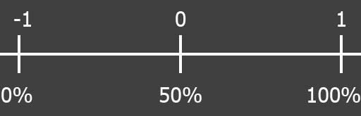
A blank normal map uses an RGB color of 128, 128, 255. The blue channel is 100% blue, this is because blue controls the areas that are flat. The Red and Green channels are set to 50% by default, causing them to be neutral. The RGB colors stand for the X, Y and Z axis' of the surface of mesh it is applied to.
It almost looks like these two images are rotations or flips of one another, but this is not the case. What a normal map does is it uses the red and green channels of a colour map to distort and transform the surface of a model to suit the artists need.
A blank normal map uses an RGB color of 128, 128, 255. The blue channel is 100% blue, this is because blue controls the areas that are flat. The Red and Green channels are set to 50% by default, causing them to be neutral. The RGB colors stand for the X, Y and Z axis' of the surface of mesh it is applied to.
Like I said earlier, the Red and Green by default should be grey to represent no change in height, and the blue channel should be mostly blue to represent 100% flat. All of these colors play hand in hand. I also said that RGB represent the axis of X, Y and Z. This may be tricky to understand at first, so I will do my best to describe how they work with one another.

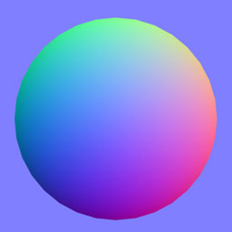
The far left image is the max geometry used to bake out a normal map on a flat plane. The result from this is the normal map on the right which will simulate a round bulge on anything it is placed on.

To best understand how this works, I have taken a tutorial straight from this web site.
http://www.bencloward.com/tutorials_normal_maps11.shtml
If you have time, I strongly recommend you read through this quickly.
Creating a Normal Map Right in Your 3D App
Did you know that you can create a normal map in ANY 3D program? You don't need any special plug-ins or exporters or extra tools at all when you create a normal map with this technique! I'll explain how to do it, but first there are a few limitations:
Your low res model must be a flat plain.
The low res model must have a planar UV projection (flat texture coordinates).
You can't use this for characters that have specific unwrapped texture coordinates.
This technique is really good for environment normal maps like bumpy ground, rock walls, bricks, metal panels, etc. I'll explain the steps to set it up for 3DS Max, but you can do the same thing in ANY other 3D program. Here's how to do it:
Open 3DS Max and create a directional light. Rotate it in world space to 0,-90,0. Set the light's color to 255,0,0 (red). Set the multiplier to -0.5.
Create another directional light. Rotate it in world space to -180,-90,0. Set the light's color to 255,0,0 (red). Set the multiplier to 0.5.
Create a third directional light. Rotate it in world space to 90,-90,0. Set the light's color to 0,255,0 (green). Set the multiplier to -0.5.
Create a forth directional light. Rotate it in world space to -90,-90,0. Set the light's color to 0,255,0 (green). Set the multiplier to 0.5.
Create one more directional light. Rotate it in world space to 0,0,0. Set the light's color to 0,0,255 (blue). Set the multiplier to 0.5.
Select each of your lights and check the "Overshoot" box under Directional Parameters so they'll light things that are outside of their cone.
Choose "Rendering->Environment..." In the Environment panel set the Ambient color to 127,127,127.
Create a free camera. Set the camera rotation to 0,0,0 in world space. Click the "Orthographic Projection" check box so that the camera becomes orthographic (so it has no perspective).
Now you create a high resolution model. Apply a material to the model that has a white diffuse color. When you render your model from the point of view of the camera, you'll get a normal map!
Here's what the scene looks like when it's all set up:

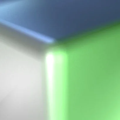
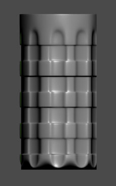
This process is here to illustrate how the lighting works in creating normal maps. Lights are used to lighten and darken areas depending on the direction they are facing. If you have something bump up on the right, usually it will appear as a 'peachy' color, the bottom will be purple, left will be light blue and top will be greenish. These lights tell the engine how the geometry needs to deform, and the intensity of the color determines how much. Keep in mind that when I say right, I am reffering to the positive X axis. The image below illustrates this rather well. From the top view (right side of the image) you can see that it illustrates the rendered out version perfectly. This file was created from the tutorial above to illustrate this function on a much simpler model.

Let’s use a cylinder to illustrate something different to look out for while creating normal maps, as well as explaining more functionality of the baking tool.

This image is the low and high poly version we will be using.
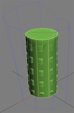
After you do the first back, you may get a 'cage' that looks like this.
A cage is what 3d Max uses to calculate how far to process information for creating normal maps. By default this one looks wild and way too far for us to create an accurate normal map with.
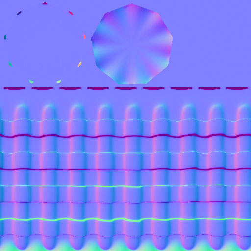
This is the normal map texture it created. You may notice the wavy appearance of the model which will give very strange results. These waves are not wanted at all. Also notice the blobby top in the middle. This will also give strange results.

This is a render of the normal map on the low poly geometry we just created. As you see, those distortions transfer over directly onto the low poly and give it this terrible result.

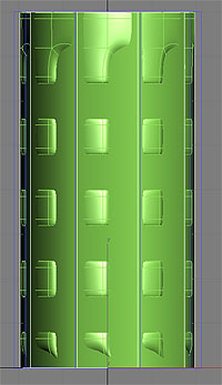
The red lines to the left are how the engine calculates the normal map. The image is distorted because the cage is. The easiest way to fix this is to 'reset' the cage. As a rule of thumb, I do this every time I bake out a normal map, the only problem is, if you have geometry that is located outside of the cage, you get red marks on your render screen. This is why the render inside max is not the blue colourful image that normal maps are. This is what the cylinder gives me when I reset it.
To reset your cage, select the low poly model that is set up to bake, and on the right under the 'Cage' option, select 'Reset'. This moves the cage back to match the low poly model vert for vert.

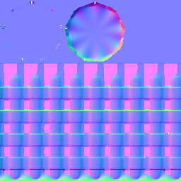
The red from this render shows up as pink and does not give an accurate normal map at all.
To make a good normal map, change the value under 'Amount' until the cage is outside the high res model. If you are not sure if the entire high res is within the cage, do a quick render, any red will show up if there is a problem.
Once you get the cage at the right distance, you will notice again that the image is distorted, although not as badly as it was originally, to fix this, you will manually have to move the top and bottom parts of the cage so they're flush with the original model. Simply right click inside of max and select 'Cage'.
The cage is flush at the top, and pushes out at the sides. Doing this forces 3d Max to render straight out in the direction of the face normals.
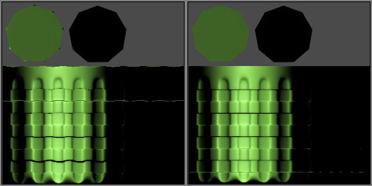
The left image is the old wobbly render created from the default cage, but the image on the right is much cleaner due to the corrected baking cage.
his is the resulting normal and the final render.

Custom cages are vital for creating the quality that you desire with certain assets.


This final render shows the normal map applied to the low poly without any lights in the scene. Once you apply a diffuse, spec and more normal map details, it will look much more believable.
With the understanding of how normal maps work, we can take a look back at the cube we did earlier. To optimize the normal map, we created a cube with only one face filling the 0 to 1 space. When we baked out the high-res, a single face was the only information calculated. Because of this, when we placed the other faces exactly over top of that square UV, they matched perfectly and created the cube that you see, however this is not always the case. It only worked with the cube because every side was exactly the same, and only curved at the corners, but let’s create a dice instead with the numbered dents in them to illustrate why this doesn't always work.
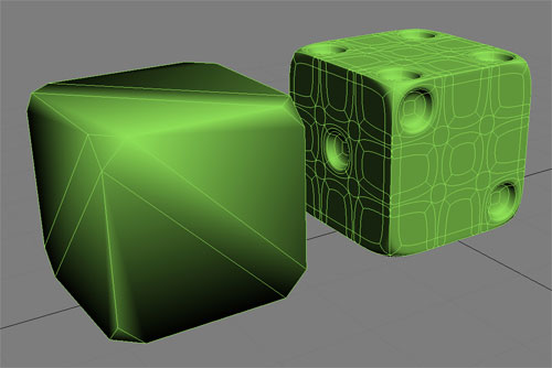
This is the low and high poly dice models. Since each face will have unique details created for the normal map, I laid out everything in the 0 to 1 with no overlapping.

Even though the UV's are not fully used, that space can be used for another asset, so instead of distorting the UV's, I kept them how they are to assure accurate texture scale.
If you encounter a problem where every face of the dice (or whatever asset you are working on) renders out with those red dots indicating an issue, first reset your cage and push it out. In this case with the dice, the problem wasn't the cage, but rather the geometry itself. Many times when geometry faces share the exact same coordinates, Max has a very hard time calculating the normal map. To fix this simply push (or scale) your object slightly so there is a gap between the high and low poly models, then tweak the cage appropriately.
Another problem you might run into is a very strange result with your normal maps. Rendered at 128X128, this is the result I got for this dice.
With the image to the left, you can see how the lines in the final render (far left) correspond to the highlights in the low poly model inside max.
To fix this problem, render out the normal map in a higher resolution such as 256X256 or even 512X512. Take the texture into Photoshop and scale it down to 128, then apply a sharpen filter to it but only once.
Quite often at VERY small texture size gives a similar result, however with certain models, a pixelated normal map can be fixed this way. In this case it will not work, mainly to do with the extreme normals of the low poly that the normal map needs to correct (corrective normal map). Try changing the smooth groups of the low poly to something more like this and try again.

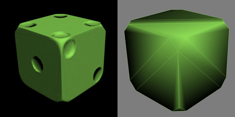
The very first thing we went over was the difference between hard edges and soft edges, but in the first example every face was the same and the model was a perfect cube, this example is much different. With the normal set to 'hard' you won't get a distortion in the normal map aside from the holes. Here is a comparison between the normal map created on a soft model vs. a hard model.

The difference is noticeable when comparing the two. If we zoom in with the renders, we can really see the differences.

The left image (soft edge) has lines that conform to the normals of the low poly model and where the right image (hard edge) does not. Also notice now much smoother and un-grainy the image on the right looks.
These are the normal maps rendered from each version. You will see how the low poly with the hard edges has a LOT of blue compared to the other one. As discussed earlier, this shows the lack of information trying to deform the surface of the model, and because of this, the result is much smoother.

(Left) soft edged low poly.
(Right) Hard edged low poly.
The reason for this is not to confuse you, especially based on the first part of this tutorial, instead it is used to show you how different situations call for different normal maps. If your normal map does not work the way you wanted it to, chances are you will have to either:
A: change the cage
B: Chance the model (adding in or taking out detail geometry)
C: Change the normals of your low poly model.

In time you will be able to predict how the normal maps will work on the asset you have.

In creating this asset, I laid out half the UV's in the 0 to 1 UV space and used the 'symmetry' modifier to make sure both sides are identical geometry and UV wise. In this example I will create a normal map using the right side, so those UV's were laid out in the 0 to 1.
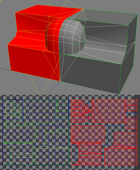
Next I selected the left half (the mirrored side which has inverted UV's (due to the symmetry process) and moved them out of the 0 to 1 uv space. The reason for this is because we do not want to double the normal map information generated. If you ever over lap UV's, offset all but one of those overlapped UV's out of the 0 to 1 space so the engine only calculates one set.

When you bake out the normal map based on the high poly, the normal map (even though the UV’s on are reversed) will appear correctly on the negative side.
We need to look at the normal map and UV's to understand how the normal maps works on both the right and left side.
When we create a normal map, it deforms the surface using RGB values. For the right side, this is correct since the normal maps were generated from these faces, but for the left side, these normals are reversed because the geometry was flipped from the right to the left using the 'symmetry' modifier. Because of this, when you have a normal map that causes the surface to bump out, the geometry that is flipped should cause it to bump in, but since the uv's are reversed in relation to those faces, it bumps it back out; it's like having 2 negatives.
The geometry is flipped (reversed), the normal maps are now reversed in relation to the faces, and both cancel each other out causing the normal map to work on both sides correctly.
(Please note that the in-game render has a spec applied to it)
Quite often when creating normal maps, you may need to render out multiple passes and comp them together, at times you may even need to manually paint out some visual issues. You should NEVER overlay a texture baked out from a high poly version onto itself to get a deeper normal map; this will cause some serious problems with the way your geometry is rendered.
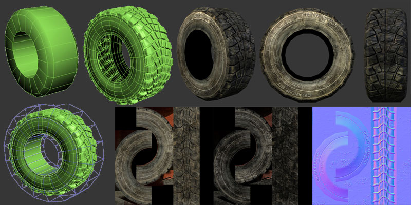
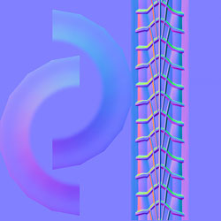
Inside Photoshop, you may be required to combine normal maps to get the look you desire. One common misconception is that all normal map details need to be baked out from a high to low poly model, but this is not always the case. If we take an example of a tire, it doesn’t make sense to model out every single detail when we can simply use a high poly to add the rough outline of the tires and their treads, and add other details inside Photoshop such as smaller tire details, scratches and words.

The low poly tire is modeled at 108 polygons.
The UV's where broken up in a few sections. A third of the tread area is layered on top of one another and the outer wall of the tire is split in half to allow for better UV use.

The low poly tire is modeled at 108 polygons.
The UV's where broken up in a few sections. A third of the tread area is layered on top of one another and the outer wall of the tire is split in half to allow for better UV use.

In order to convert this into a normal map inside Photoshop, you need to download a Nvidia plugin located here.
http://developer.nvidia.com/object/photoshop_dds_plugins.html
This tool is very easy to get the hang of, but for this tutorial I will cover just the basics.

This is the preview window which shows you roughly what your normal map will look like.
The samples represent how soft or sharp the normal map will be, 4 samples being the sharpest. Most of the time the invert options should be turned off. Scale refers to how much the normal map bumps out. Experiment with this to fully understand which number best suites your needs.
Average RGB will usually give you a good result, but if you turn on any options in #4, this will be disabled.
You are given more control with these options about which colors should be used if using an RGB texture.
When previewing your render, these options can assist you in ways such as a moving light to see how it plays with the normal map.
Height is almost always what you will be using with this option. Very rarely will you need to use this.
The preview window. Be warned that this function has been known to crash Photoshop.
When creating your normal map, everything has to be flattened to one layer. I strongly suggest flattening it, copying out the layer, un-doing the flattening then paste the saved layer back into Photoshop on top. The reason for this is because quite often these layers can assist you with your diffuse and spec maps, and having layers gives you MUCH more control over the values.
When you have everything all done and your black and white texture converted into a normal map, it is time to overlay it onto your normal map.
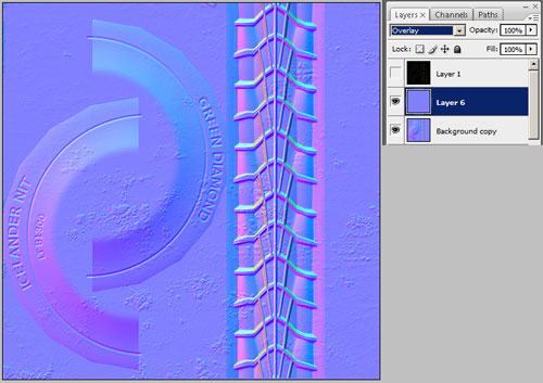
To overlay your texture, place the original on a bottom layer and the new normal map on the top. Under 'layers' with the new texture layer selected, you will see a box which reads 'Normal', change this to 'Overlay'.In order to finish this overlay, flatten the layers and copy it out, undo the flattening and paste the texture onto a new lay as done before. Since we placed another normal map over the original, we need to use the 'Normalize only' function located under option #4.
Pressing this option deactivates every other settings in the plugin. When you hit 'OK' you will notice the colors of the normal map change slightly, this is normal.
After that, you're done. Save out the texture and see your results.


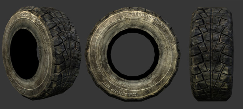
The diffuse texture was very quickly done, but this gives a rough idea of how you can use a highres model to create details on a low res model

This render is in UT3 so we can see how an engine actually processes the picture.
I hope this little tutorial has helped you out. i thank you for your time.